I’m writing this blog as a reminder for myself as i get asked a lot of questions that is not technical related but more product specific. So instead of clicking different links to understand the diferences i decided to put them all in one place with brief description to help me remember!
First and formost a common question is the DNA licensing, DNA licesning is like a minefield and I think I have just about understood this enough to get my head around it. The role I do, especially SD-WAN as my stronger subject, i need to know the information.
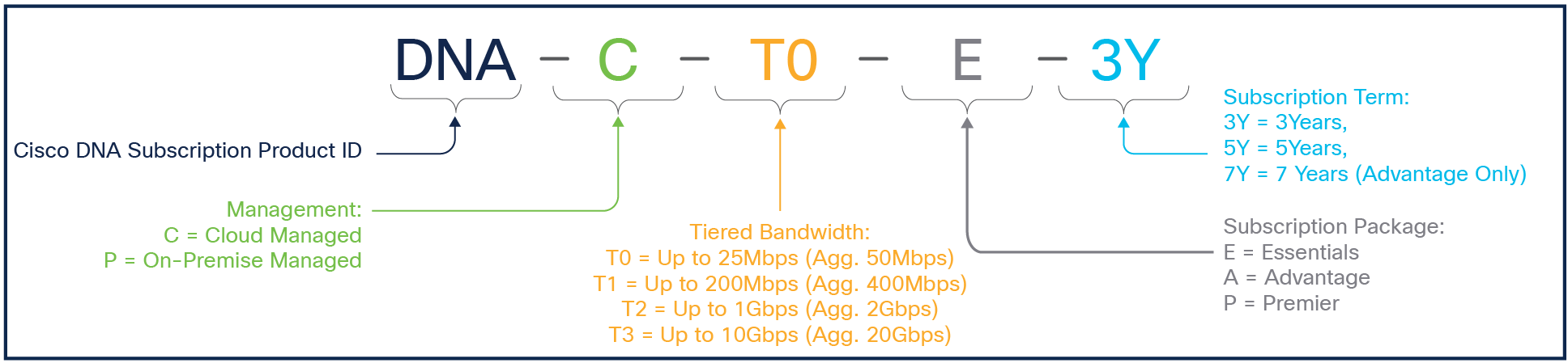
So lets start by understanding how Cisco DNA licesning works for routing and SD-WAN:
Green – illustrates the type of DNA license, whether it will be on prem or managed in the cloud.
Orange – is the Tiered license so you know which bandwidth you need to purchase. This is important – as you can see the aggregate doubles. This is to account for symmentrical upload and download.
Grey – The type of license in terms of package, Essentials, Advantage etc. The difference is essentially the capabilities you want to achieve or do. I will explain a little more in that later.
Blue – is how long you want the license to last.
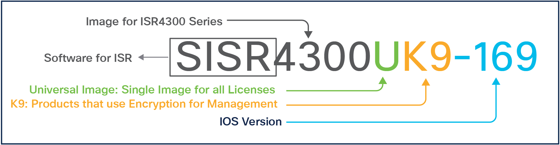
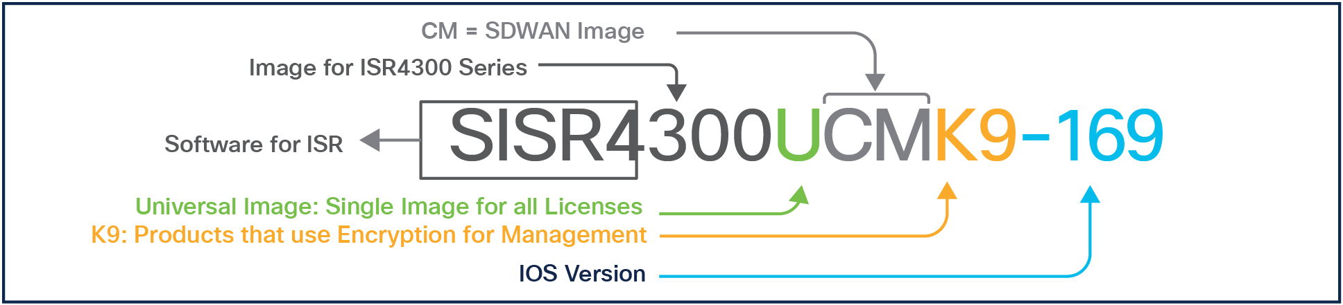
Understanding the Cisco DNA for SD-WAN and Routing and Cisco IOS Product Part Codes
SDWAN image above
Bandwidth Entitlement
There’s two ways to work out the bandwidth – the first method is to add all the upload and download together which works the total Aggregate bandwidth – based on the aggregate bandwidth you can then choose the correct tier using the aggregate bandwidth number.
Alternatively you could add the the total aggregate bandwidth then divide by 2 and based on that number you choose the tiered bandwidth which is the up to XXMbps.
One thing i have learnt when creating a BoM is some of the tiered license will not show up if the router is not able to push that amount of throughput. An example is when you are trying to create a BoM for Cat8200, you cannot choose the T3 license which pushes up to 10Gbps/ 20Gbps Aggregate as the router is not possible.
Now, earlier I mentioned there are different types of DNA license available and what are the main differences?
To begin on the SD-WAN world, we have the following:
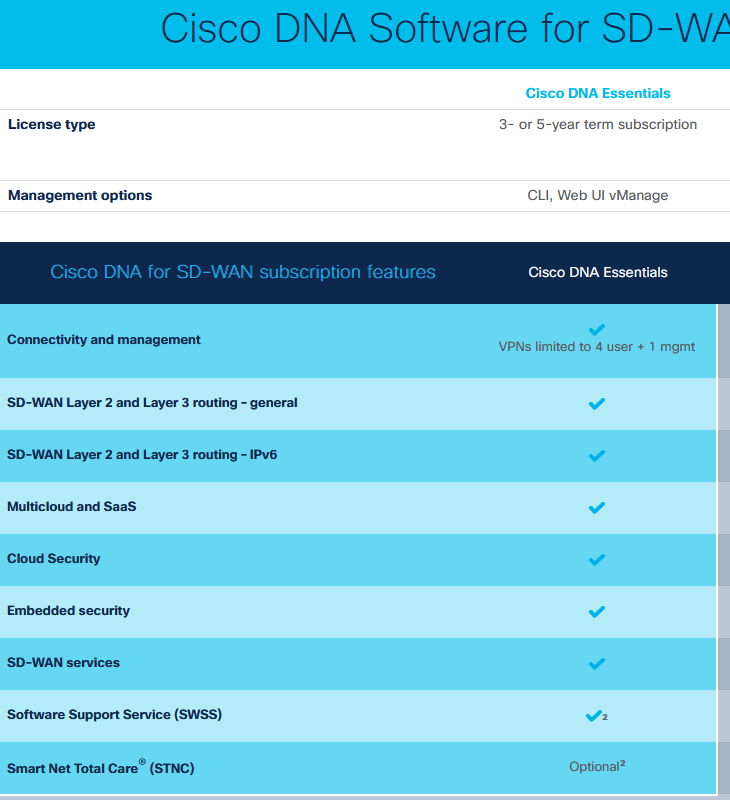
DNA Essentials
DNA Advantage
DNA Premier
DNA Essentials
With DNA Essentials you have the basic DNA license for SD-WAN, I will not list out all the features but one thing to be aware of is that you only get up to 5 VPNS/VRF overlays in the SD-WAN world. 4VPNs of your choice and one for MGMT.
DNA Advantage
With DNA Advantage, you dont have any restrictions of VPNs/Overlays other than the maximum supported which is VPNs 1–511, 513–65530—Service VPNs, for service-side data traffic on Cisco IOS XE Catalyst SD-WAN devices.
You also get all the Essentials plus Advantage together, Advantage offers the following below:
DNA Premier
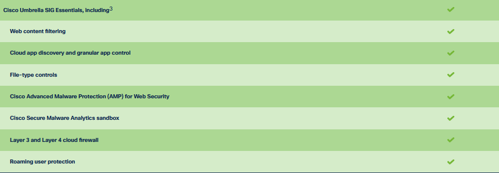
This inclused Essentials and Advantage, the main difference is if you want to go to the world of SASE with Umbrella capabilities then this is the license you would be better off. I have only added what the Premier offers, remember it includes Essentials and Advantage plus the below in Green
DNA for None SD-WAN
Now with SD-WAN licensing out of the way, there is a subtle difference with None SD-WAN which i will call it autonomous mode as Cisco image now allows you to configure it in SD-WAN mode (controller-mode enable) or autonomous mode (Normal Routing).
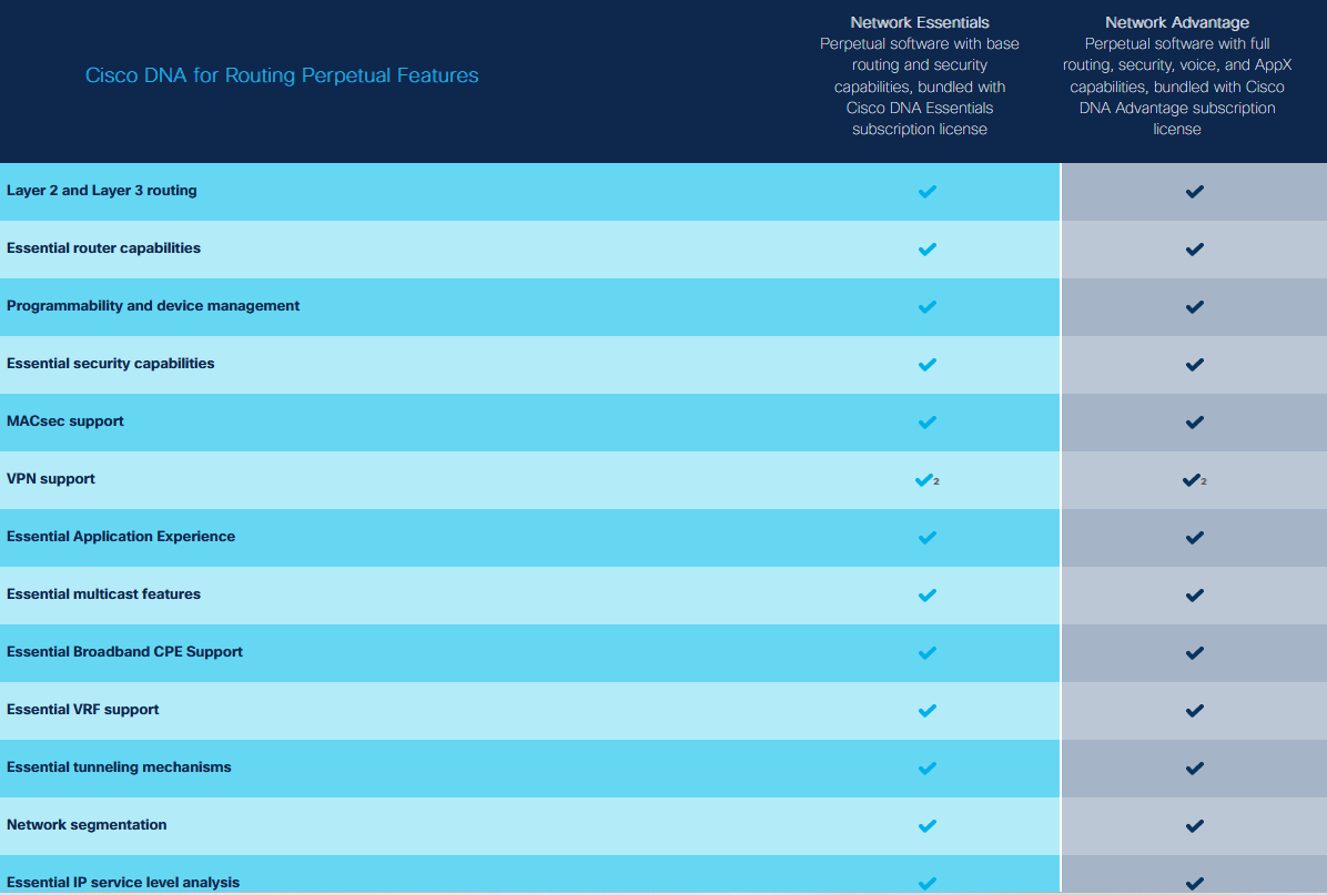
When you purchase a router which will be operating in Autonomous mode, you HAVE to buy a DNA license. So this means you either need to buy DNA essentials or Advantage based on the capabilities and features you need. So if you required to run PIM (Multicast) straight out of the box then it will be Advantage straight away. Once the duration of the license is over, you can then move to the DNA Routing Perpeptual license which doesn’t cost any money afterwards.
Another thing I wanted to mention is the bandwidth tier – You just need to choose the lowest bandwidth tier IF you are not running IPSec or encryption. So just pure routing and no encryption then you can choose the lowest tier which is T0. However if you do choose encryption then it is the DNA license you need to choose the DNA Essentials or Advantage.
I may have previously touched up on CoR in my previous blogs, but I would like to dedicate a blog post specifically about CoR.
So what is CoR actually?
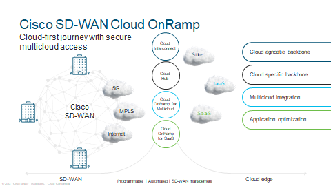
SaaS – Uses real-time, granular analytics for each application to steer users onto the best-performing path for optimal application performance. In another words, best path available to your Cloud environment.
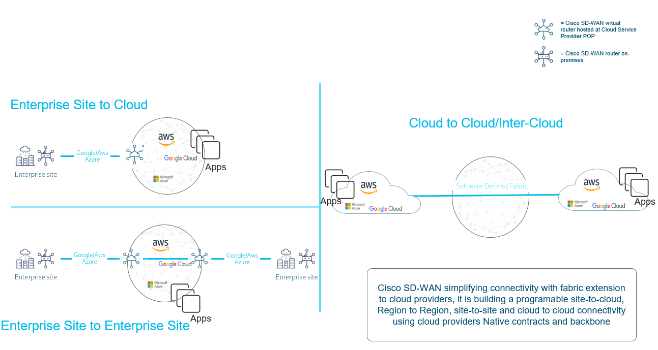
COR for Multicloud –Cloud Hub -Extend the WAN to a public cloud with a single SD-WAN fabric. Apply consistent policy to cloud workloads.
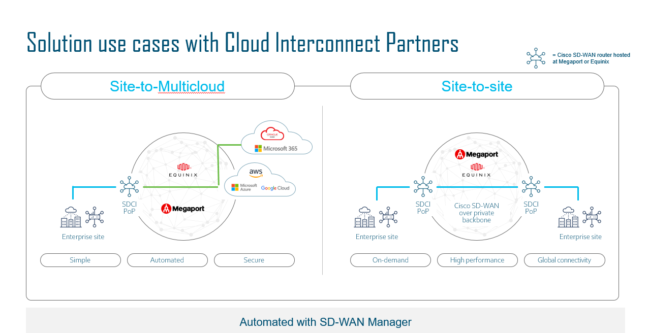
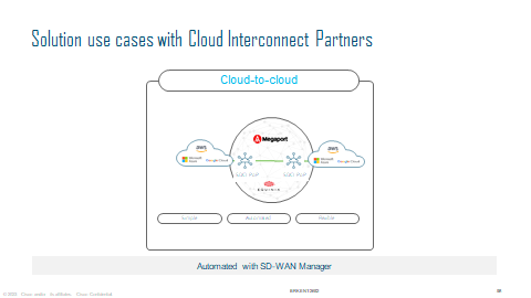
Cloud Interconnect—Automate on-demand connectivity between multiple sites and to leading cloud provider networks, directly from your SD-WAN controller.
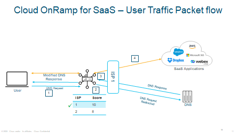
CoR SaaS
1 – All transports that are able to provide SaaS access will request DNS on their Transport VPN 0.
2 – HTTP/S pings are sent to the SaaS provider to begin measurement.
3 – Scores are measured with a best score of 10.
As you can see the example of a CoR traffic flow in how it all works. ISP 1 has the best score therefore it will choose ISP 1.
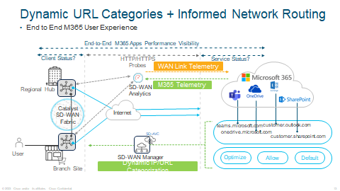
An example of CoR for Microsoft 365, Dynamic URL Categories is where you can multiple Microsoft Service offerings such as Teams, Outlook, Sharepoint etc.
With Informed Network Routing, this is end to end telemetry for the Services I mentioned above, this allows CoR to select the best path depending on the SaaS application with a score.
With CoR, you can also monitor Webex where Edge router will sends HTTPS probes to Cisco Webex Responders across Cisco’s global regions.
Webex API enhances the classification of traffic that needs to go to the best performing Webex region.
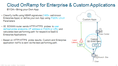
You can even configure and setup your own CoR for your own custom applications usning NBAR or your own FQDN application. Same principle applies with HTTPS probes.
Examples and uses cases of CoR:
CoR Multicloud
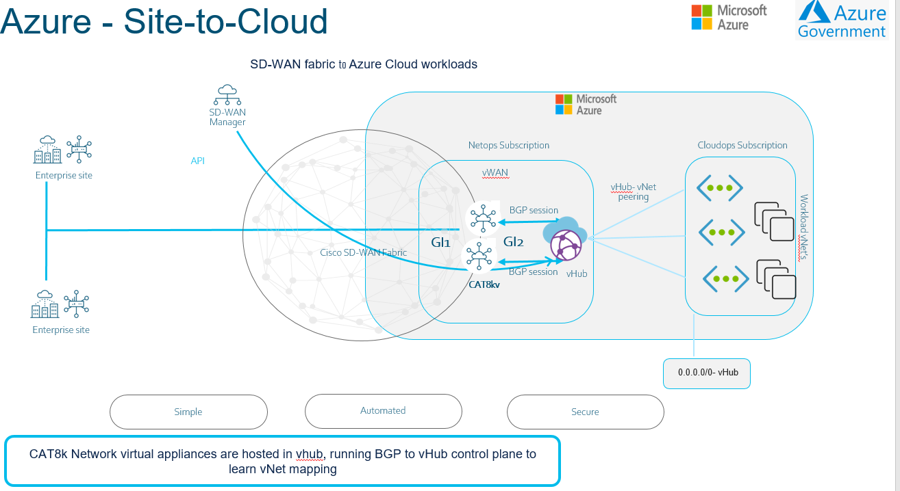
In this model we spin up virtual routers (Cat 8000v) inside the cloud service provider to extend the SDWAN fabric all the way to the application and networking of the CSP. This can be automated by developing workflows in SD-WAN Manager. Workflows is a new tool that helps you click and configure features without the need of defining Groups of Interests like we use to have. This workflow allows the user to configure without the expert knowledge required in the Cloud world. This allows network operators to easily deploy the SDWAN service in each of the cloud service providers. SD-WAN Manager can then deploy and bootstrap the cat8000v in the CSP. Within minutes your SDWAN environment will have access to your key applications running in the CSP.
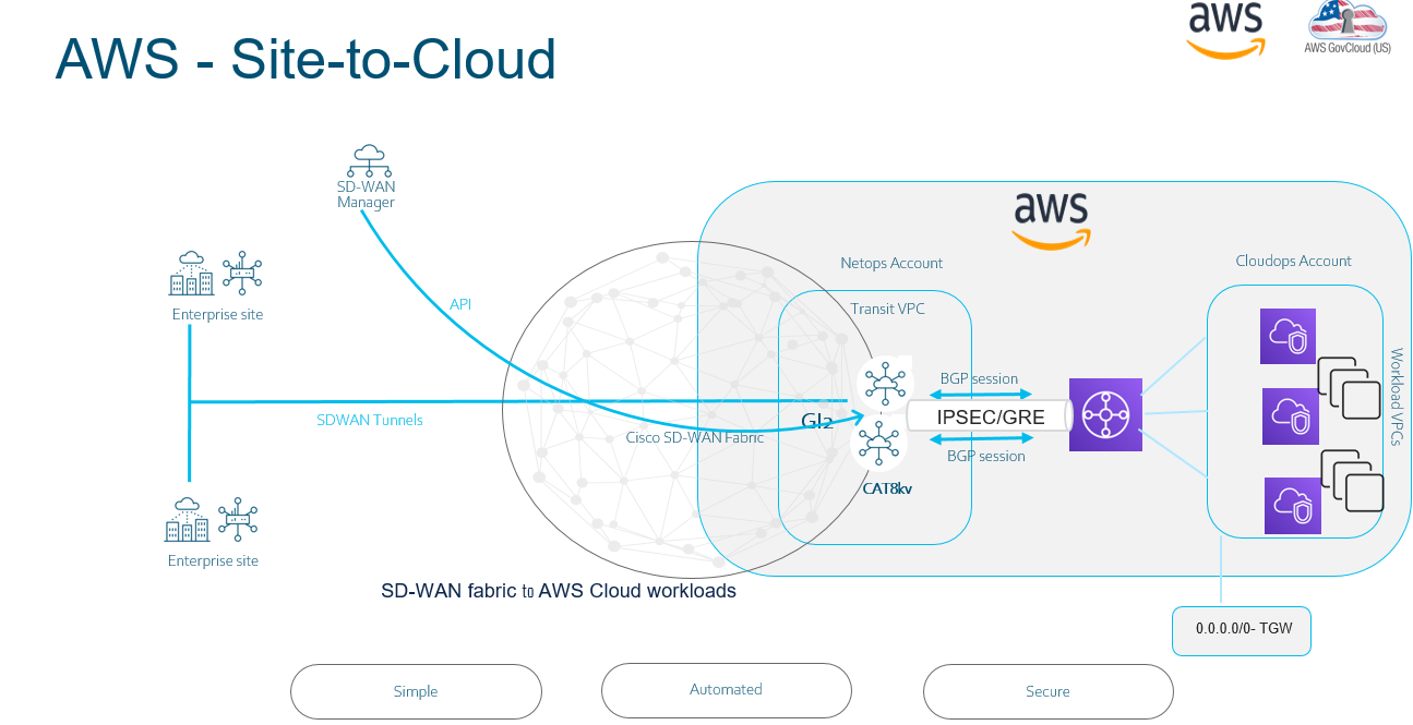
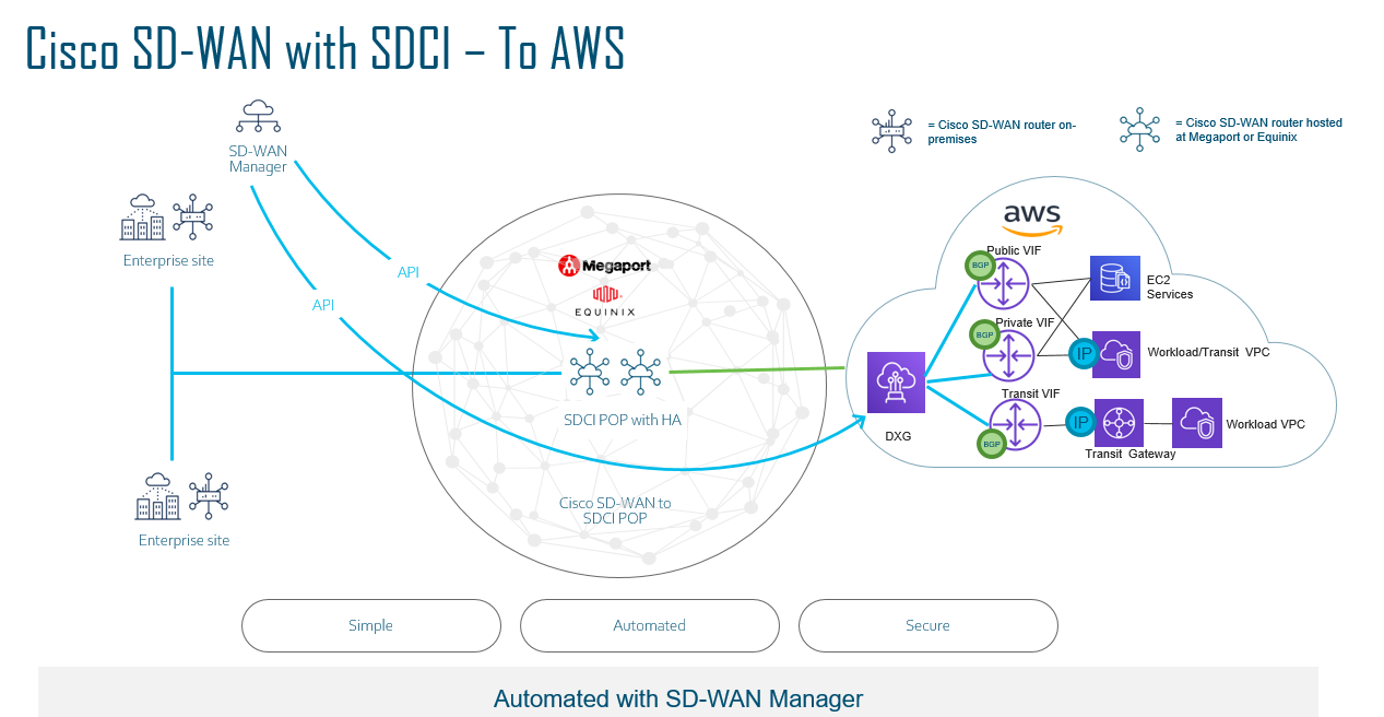
AWS
There is different use cases when you are spinning up within the AWS environment. Below are a few examples in how you can leverage SD-WAN and AWS.
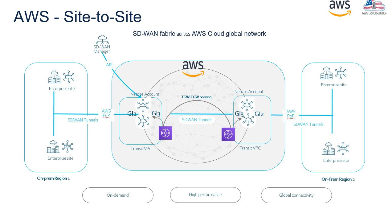
The above example above illustrates where you have a AWS region with Cat 8kv deployed in HA, but you also have another region for example in USA. So to connect between two regions you can spin up Transit Gateway so the SD-WAN fabric can be extended.
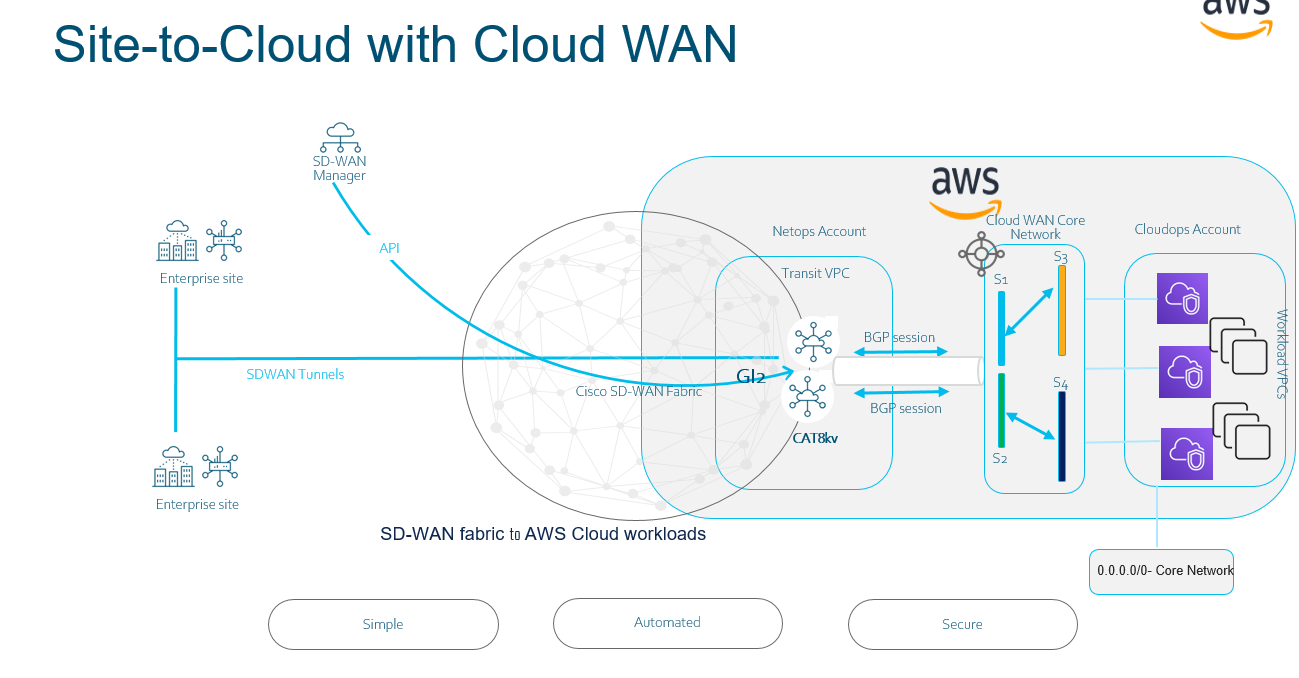
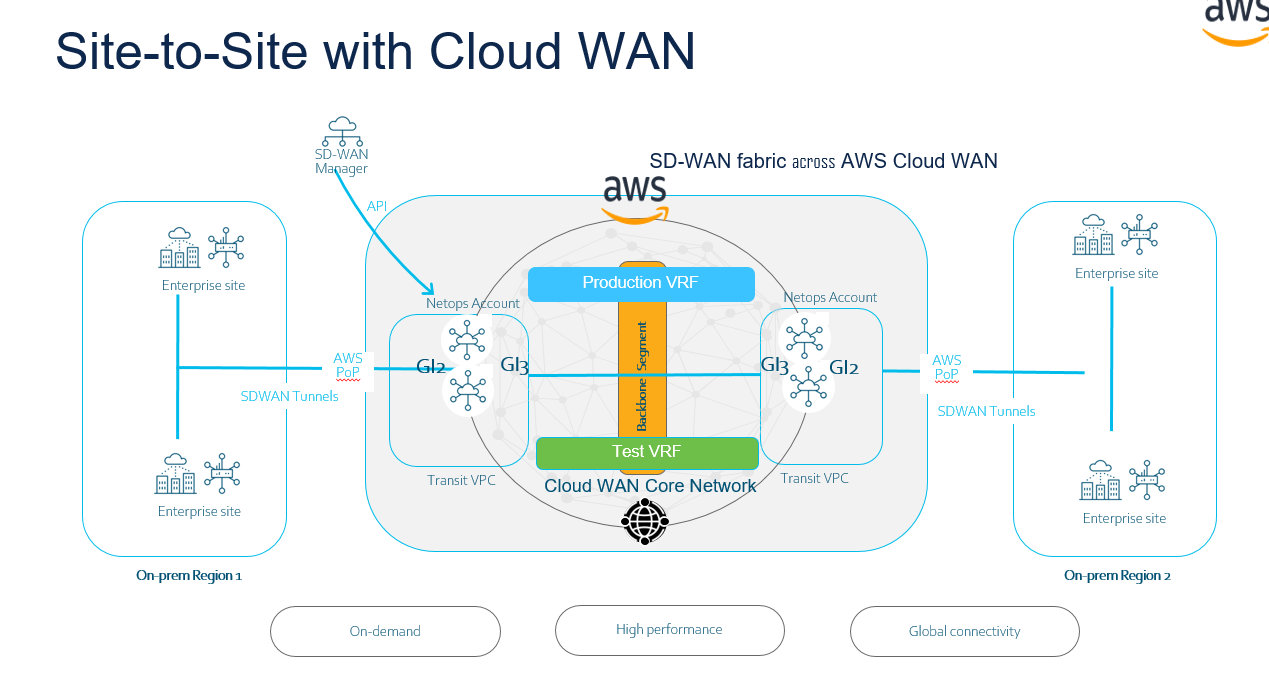
AWS Cloud WAN is a managed wide-area networking (WAN) service that you can use to build, manage, and monitor a unified global network that connects resources running across your cloud and on-premises environments. It provides a central dashboard from which you can connect on-premises branch offices, data centers, and Amazon Virtual Private Clouds (VPCs) across the AWS global network. You can use simple network policies to centrally configure and automate network management and security tasks, and get a complete view of your global network.
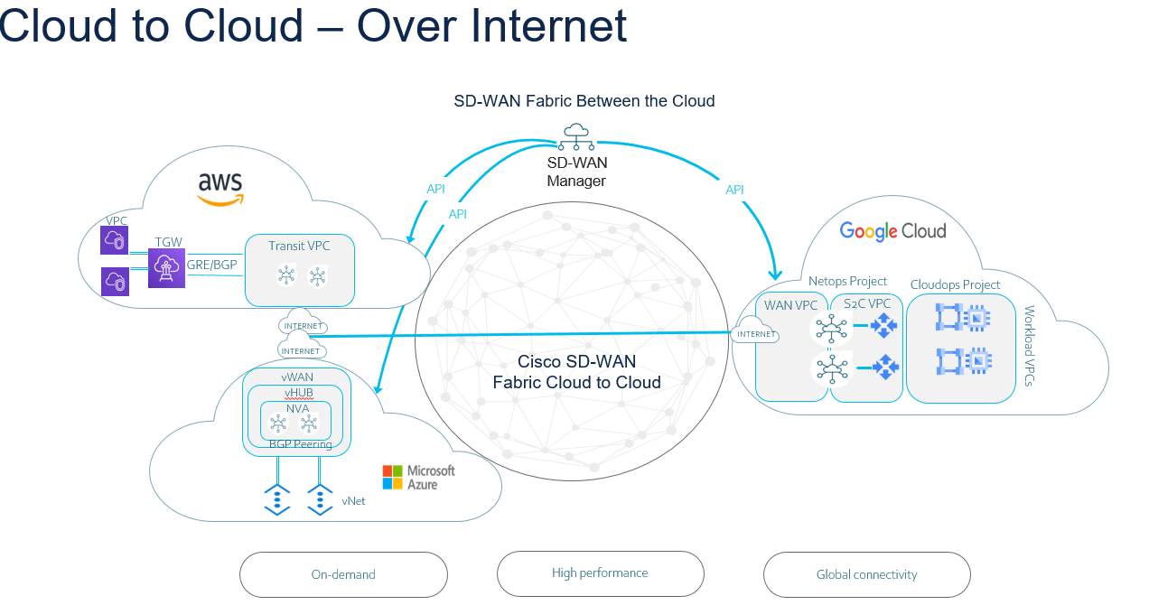
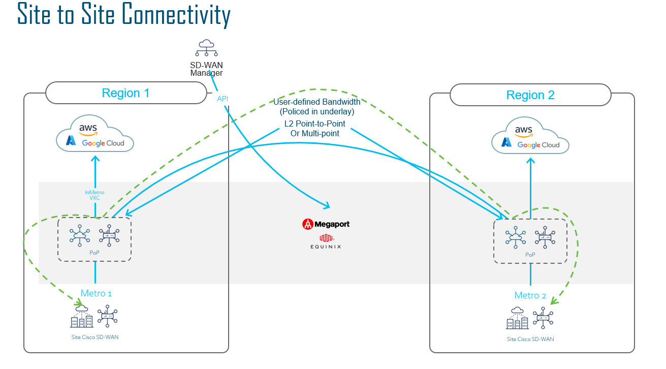
With SD-WAN you can even connect your other Cloud providers with other cloud providers as part of your SD-WAN fabric. The example below basically illustrates if you use AWS for a specific workload and Azure for another Workload.
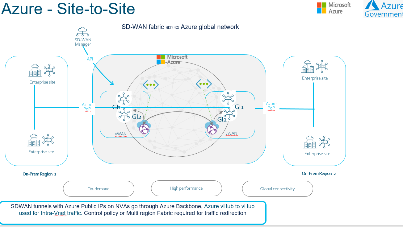
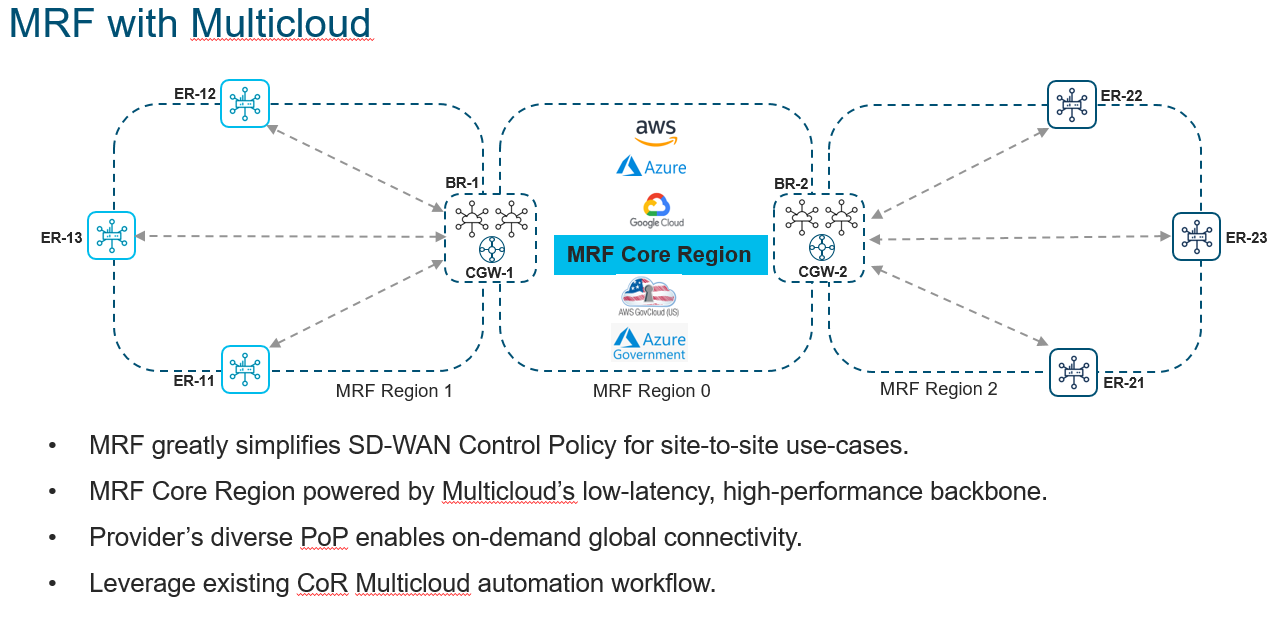
I’ve previously wrote a blog about MRF, but you can even implement Multicloud acting as your Region 0 (Backbone) from a design perspective.
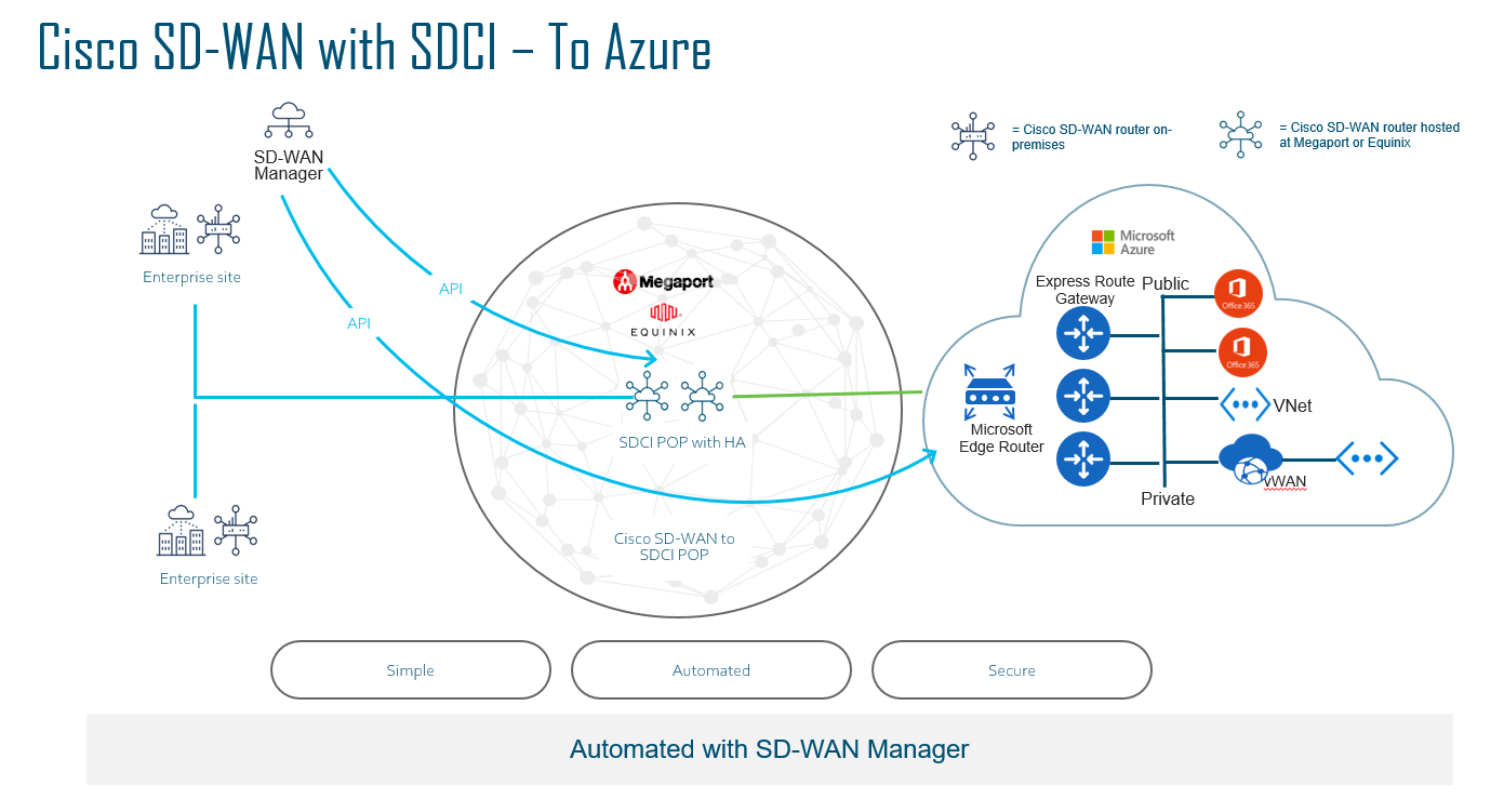
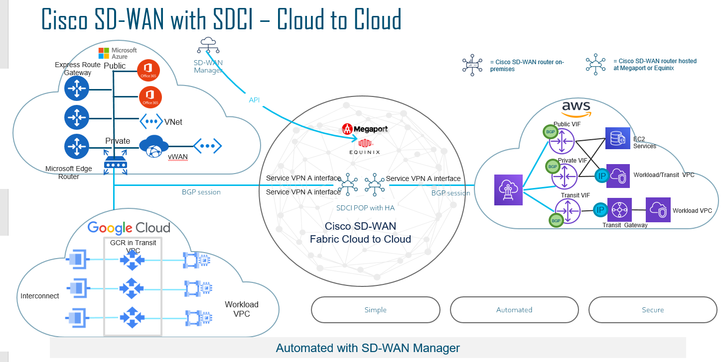
Cisco has partnered with Equinix and Megaport as the backbone provider. Essentially if you wanted a private back bone in your core network, you could utilise either partner and spinning up a Cat 8kv.
So instead of relying on the Internet as your transport for a Cloud to Cloud SD-WAN fabric, you can utilise the high speed backbone to connect back to your Cloud Provider. Most providers will usually build a Private MPLS L3VPN network in order to connect to the cloud provider, using Interconnect providers, you do not need to rely on your local ISP’s to do this.
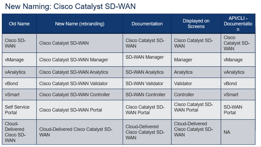
Before I begin explaining what Catalyst SD-WAN is, I’d like to address the new naming for the core components.
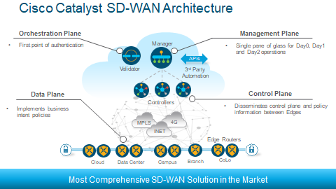
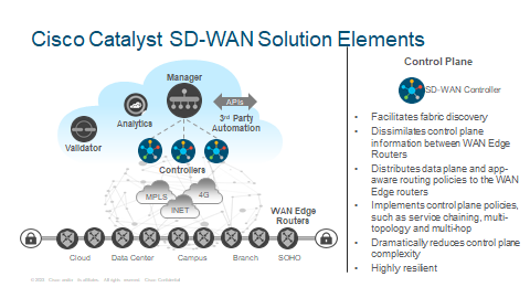
The above is the SD-WAN Architecture.
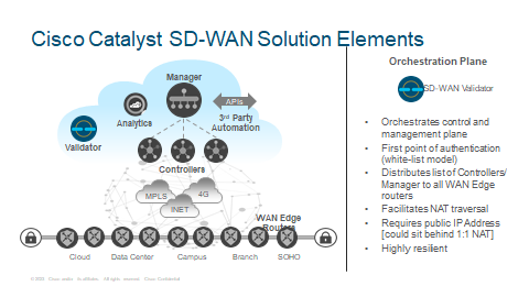
Validator
Cisco Validator is a multitenant part of the Cisco Catalyst SD-WAN fabric. It allows the discovery of the control and management sections of the fabric by leveraging a zero-trust certificate-based white-listed model.
It automatically distributes the list of Controller and the Manager system to the WAN Edge routers during the onboarding process. For situations where Controller, Manager system or the WAN Edge routers themselves are behind NAT, Validator provides the function of NAT traversal, by allowing learning public and private IP addresses.
The discovery of public and private IP addresses allows establishing connectivity across public and private WAN transports. Validator itself should reside in the public IP space or reside on the private IP space with 1:1 NAT.
When delivered as a cloud service, Controller are redundantly hosted in AWS Cloud by default. When deployed as an on-prem solution by the customer, it is the responsibility of the customer to make sure the design allows for resiliency. I have written a post about on-prem SD-WAN below:
http://jaychou.co.uk/?p=618
Controller
Cisco Controller are a scale-out control plane functions of the Cisco Catalyst SD-WAN fabric. Controller allows fabric discovery by running the Overlay Management Protocol, the OMP, between themselves and between themselves and the WAN Edges. Together with WAN Edges, Controller act as a distribution system which allows relevant information that is needed in order to establish data place connectivity beweeen WAN Edge to WAN Edge.
This information includes service side reachability, transport side IP addressing, IPSec encryption keys, site identifiers etc..
Control Policies acting on the control plane information are made locally on the Controllers and not the WAN Edge devices.
These control plane policies can implement service chaining, various types of topologies and dictate how the traffic will traverse.
A common similar comparison is the BGP Route Reflector in the traditional networking world. The Controller acts in a similar way except for the Control Policies will affect the Controllers.
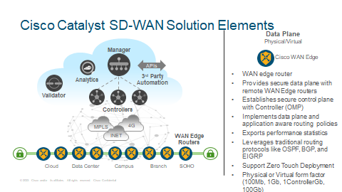
WAN Edge
Cisco WAN Edge routers are the data plane elements of the Cisco Catalyst SD-WAN fabric. They are in essence WAN edge routers positioned everywhere SD-WAN fabric needs to be extended to. WAN Edge routers are responsible for encrypting and decrypting application traffic between the sites. As mentioned earlier, WAN Edge routers establish control plane relationship with Controller to exchange pertinent information required to establish the fabric and learn centrally provisioned policies. Data plane and application aware routing policies are implemented on the WAN Edge routers.
WAN Edge routers leverage standards based OSPF, EIGRP and BGP routing protocols for learning reachability information from service side interfaces and for brownfield integration with non-SDWAN sites. For data plane redundancy, WAN Edge can be configured in L2 redundancy such as VRRP, even on a per-VLAN basis.
Zero touch deployment also can be utilised which relies on the use of signed certificates installed in the on-board temper proof module, the TPM) to establish unique router identity.
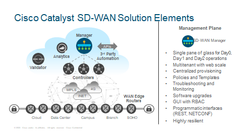
Manager
Cisco Manager provides single pane of glass for Day0, Day1 and Day2 operations. Its multitenant web-scale architecture that solves the needs of the enterprises and the service providers alike.
Some of it’s key functions include centralised provisioning, centralized policies and device configuration templates, ability to troubleshoot and monitor the entire environment and perform centralized software upgrades on all the fabric elements. Manager GUI allows segregated administrative access by implementing RBAC for proper roles and responsibilities. Performance statistics can be exported into external systems or to Cisco Analytics tool for further processing and deeper insight such as ThousandEyes WAN Insights (Sales Pitch!).
Fabric Operation
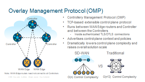
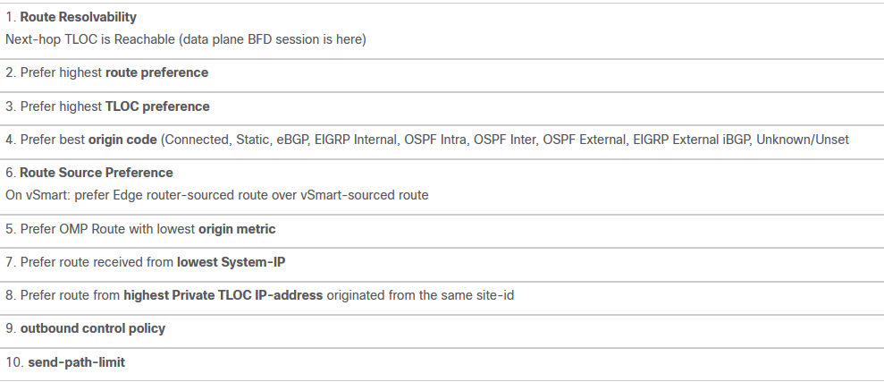
OMP is the routing protocol for SD-WAN, created by Cisco. It is essentially the same as BGP in how it works with the best path selection.
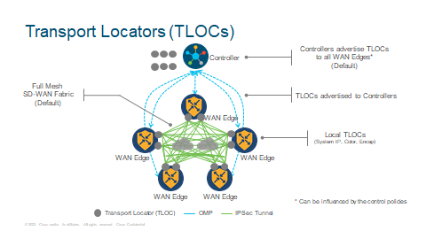
TLOCs
Cisco Catalyst SD-WAN can build secure overlay fabric on top of any public or private transport, such as MPLS, Internet, 4G LTE, Satellite, point-to-point circuits and so on. This gives the customer the flexibility without having to rely on one Service Provider and no matter which country you are in you do not need to purchase expensive backhauls. IPSec encryption is used for the secure overlay fabric. Transport locators or TLOCs, represent abstraction layer for defining IPSec tunnel endpoints. Cisco Catalyst SD-WAN fabric leverages [system IP, color, encapsulation] for defining IPSec tunnel termination endpoints. This allows independence from individual transport IP addressing.
TLOCs are advertised as TLOC routes in the OMP messages between the WAN Edge routers and the Controller. Controller reflect TLOC reachability between the WAN Edge routers across the fabric. In the absence of control policies on the controllers, all TLOC routes get advertised by the controllers to all WAN Edge routers. Control policies can be used to block certain TLOC route advertisements or modify their attributes before passing them along. Once advertised, WAN Edge routers can construct direct IPSec tunnels between themselves. By default WAN Edge routers construct a full mesh topology.
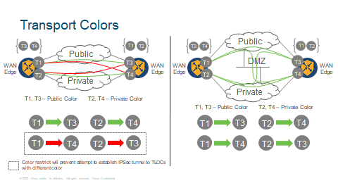
Colour
As color is one of TLOC attributes (along with system IP and encapsulation), Cisco Catalyst SD-WAN fabric allows creating a setup where WAN Edge routers do not attempt to establish secure IPSec tunnels with remote TLOCs having a different color than a local TLOC. This is called restrict option. With restrict, WAN Edge routers will not attempt building secure IPSec tunnels between private and public transports and as such, Manager will not report any downed connections.
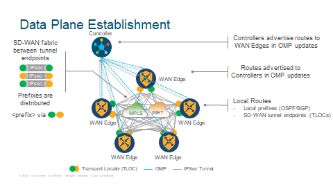
Data Plane Establishment
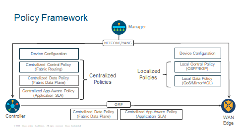
Policy Framework
This is a good example of where you would configure your policies and what will be affected. With Centralised Policies this is will be configured and sent to the the Controller. With Localised Policy, this will be done and affects the Data Plane (WAN Edge).
Data policies are primarily used to override fabric routing behavior with specific instructions in regard to next-hop, outbound transport, service insertion and so on. They can match on any of the 6-tuples (including DSCP value) in the TCP/IP headers or on one of the DPI signatures if it had been turned on. Application aware routing policies can enforce prevent application traffic of interest from being sent down the tunnels that do not satisfy the loss, latency or jitter SLA thresholds as defined by the administrator.
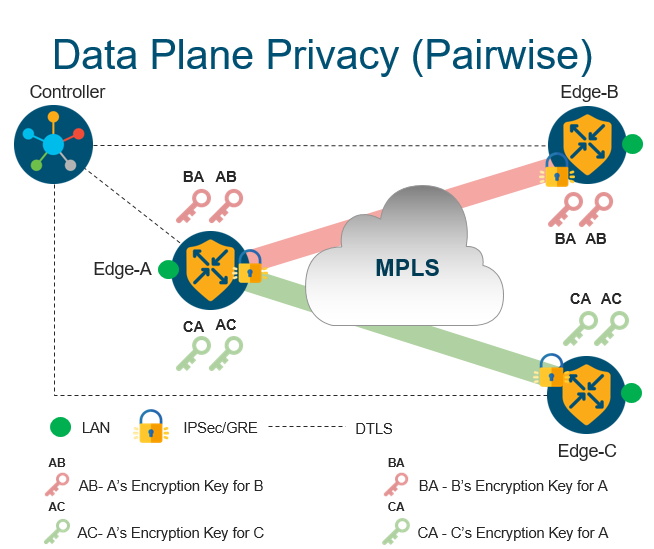
Data Plane Privacy
Each WAN edge will create separate session key for each transport and for each peer
Session keys will be advertised through Controller using OMP
When Edge-A needs to send traffic to Edge-B, it will use session key “AB” (B will use key “BA”)
Backward compatible with non PWK (PairWise Keys) devices
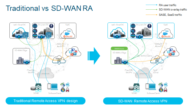
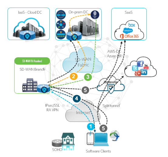
Traditionally, RA will tunnel through one Security Edge Device at the perimeter. Typically this provides challenges such as:
Deploying SD-WAN means RA will be treated as a separate network.
VPN hardware may cost more with more users using the service.
Separate Management Plane.
Separate policies for RA and Corporate users.
Traffic traverses through DC which can lead to poor Application Experience.
Traditional RA is stiched to SD-WAN network at the DC today.
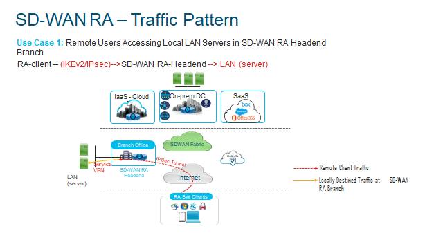
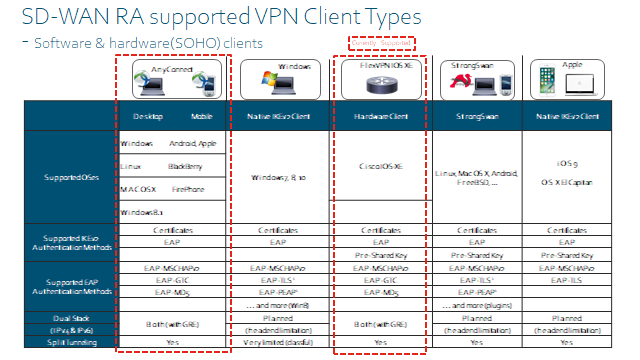
SD-WAN Remote Access Overview
Cisco RA uses FlexVPN, FlexVPN is another method to configure VPN but in a much simpler manner. If you have configured DMVPN Phase 3, you will realise how much configuration is required. FleVPN simplifies this and uses IKEv2.
You deploy a headend device (Router) at the head end network such as where all your applications or services will be ideally.
IOS-XE supports FlexVPN(IKEv2/IPSec)
SSLVPN
As of v20.12 SSL VPN is now supported.
IOS-XE SD-WAN devices can support RA Headend device.
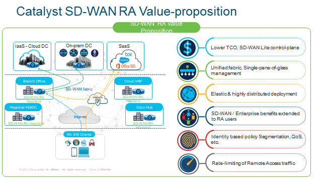
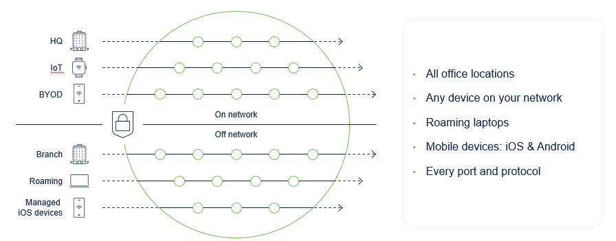
Just going to throw the Sales Pitch into why you would want to use RA!
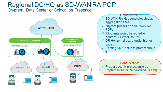
SD-WAN RA – Deployment Considerations
Static IP on the SD-WAN RA Headend for inbound RA VPN connections.
Dedicated non-TLOC WAN interface for RA, for Geo-load balancing and also you can configure inbound ACL to restrict traffic to IKEv2 and IPsec as well as now SSLVPN.
Shared TLOC interface with static public IP
SD-WAN RA – Workflow
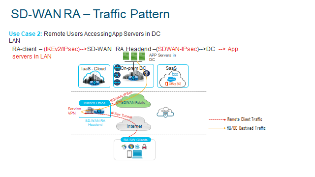
1 Remote user connects to teh RA headend and requests a IPec/SSL VPN connection
2 RA Headend authenticates clients with a certificate or PSK.
3 User/Group policy determines the level of access and Client/Subnet is pushed out.
4 IPSec virtual interface (per RA user) is created and pushes the IP addresss and DNS etc
5 Full or split tunnel routes traffic to the allowed subnets based on the policy set.
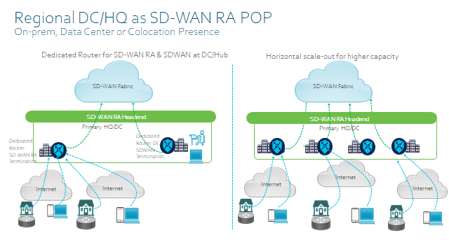
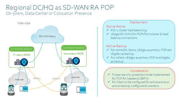
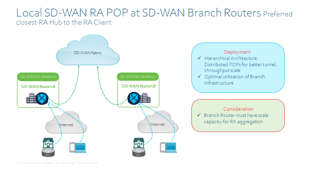
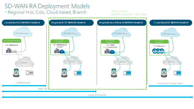
SD-WAN RA Deployment Models
Platform Support
Final thing to consider is the design when implementing RA, is the Headebd device – remember it will need to serve the Service side as well as the usual NAT/DIA sessions on top of the SD-WAN overlay Control Plane as well as Data Plane. So it is best to size appropriately so the box doesn’t set fire to itself!
Before I begin to explain and go through what Cisco Umbrella is I’d like to briefly explain what SASE is so this helps to understand the need and why Cisco Umbrella.
SASE is a different type of achitecture that brings Networking and Security servives as one solution. Designed for strong security from edge to edge, this includes DC’s, branches, remote workers etc.
DNS Security
The first line of defence with Cisco Umbrella is DNS security. You essentially point your DNS to Cisco’s Umbrella DNS server: 208.67.222.222. DNS Security provide the follwing :
Blocks domains associate with malware, phishing, command and control callbacks anywhere. (C&C servers are used by cybercriminals to send commands to systems compromised by malware and received stolen information from the target network)
Stops threats a the earliest opportunities as well as malware if it is part of the URL/website.
Cisco Umbrella uses different types of models to track any potential harm/threat.
Co-occurance model – Identifies other domains that is looked up in rapid succession of a given domain. An example is when a specific domain that is malicious also has other domains tied/looked up with the malicious domain. In essense domain guilty by intereference.
Natural Language processing model – domain names that spoof terms and brands.
Spike rank model – detects domains with an unual high spike of traffic.
Predictive IP space monitoring – Analyses how servers are hosted to detect future malicious domains.
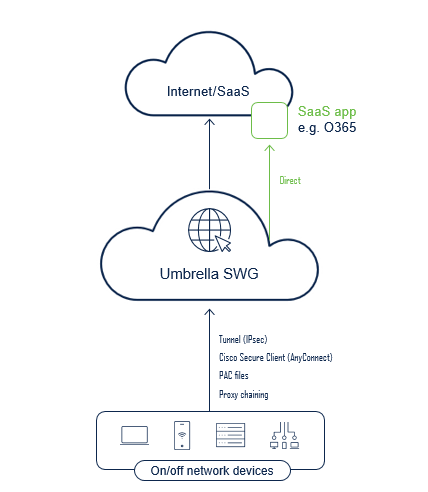
Secure Web Gateway
SWG allows the user to protect the following:
Anti-Virus and AMP Malware scanning (Advance Malware Protection) – Scan and detect a broad range of malware and viruses which avoids infection and stops any attacks. AMP is another anti virus product for end points. Working together to make sure enterprises are secure twice.
File Type controls – Prevents downloads of specific files, .exe files etc, also provides visibility of file types.
SSL decryption – Decrypt HTTS traffic, without HTTPS decryption, you will not be able to see the URL.
Category and URL filtering for Content control – Content categories is used for ‘acceptable use policies’ for enterprises. You can filter based categories such as ‘adult, Alcohol, News etc’. SWQuses Cisco’s Talos category which is the biggest security group for online activity.
Threat Grid file sandboxing – Sandboxing is used when there is a new threat that has not been identified/ categorised without much information will be sent to Cisco Umbrella Sandbox in the cloud to be tested and see what is happening.
App Visibility and control – Can block posts/shares on Social Media, block attachments to webmail apps, and blocks uploads to cloud storage, collaboration, office productivity and content management.
URL reporting – Visibility for compliance, monitoring and investigations. You can view the URL details by network, user , device and date for : trends, monitor activities and investigate incidents.
Cloud-Delivered Firewall
This is an Outbound firewall, meaning this will only work on the egress side as it leaves Umbrella. If you had other services in a DC or HQ which also have servers and requires users coming inbound to access, Cloud Firewall will not work.
It has the following capabilities:
L3/L4 Firewall – L7 capabilities
DPI in NBAR
IPSec only – When you engage Cloud firewall etc then an IPsec tunnel is setup to Umbrella SIG.
Multi-geo DC support/location
Auto failover should primary DC fail – This is done by setting a standby tunnel to another DC using Anycast.
Firewall logs are exported to AWS S3 bucket.
An example is SWG blocks MS Web traffic and the fierwall blocks it Voice/video traffic.
Order of operation is also important with the same rule as when you configure ACLs.
How this works……
Enterprises can choose which data center they wish to utilise Umbrella as their exit point, advantage of Umbrella is that you do not need to build backup IPSec tunnels as this is done automatically. So if a data center fails then the IPSec tunnel will automatically move with minimal down time.
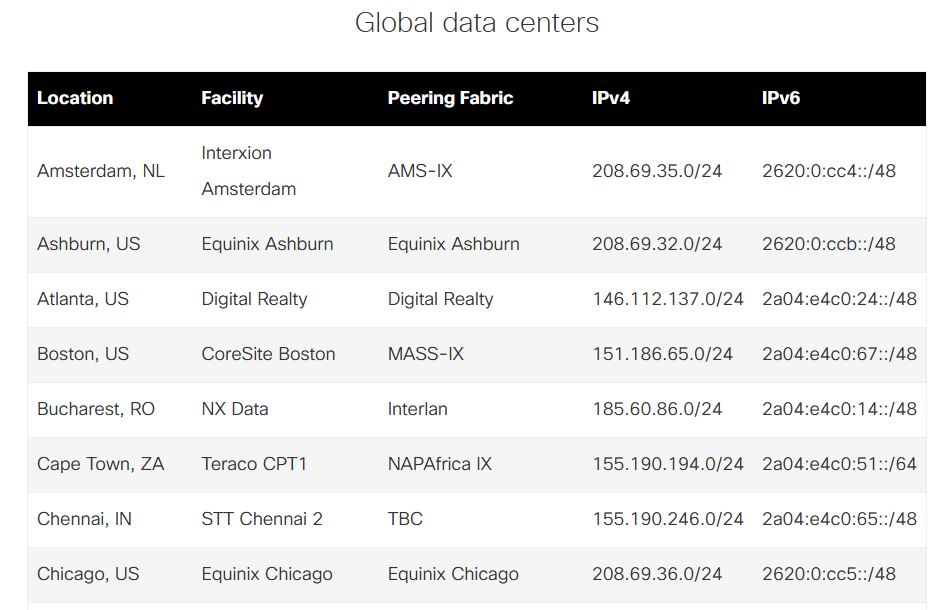
When Customers choose Umbrella, Cisco will provide a static Umbrella Egress IP from the range of 146.112.0.0/16 and 155.190.0.0/16. These IPs will be unique to one per customer.
IPSec Capacity
Cisco offers a maximum of 250Mbps in each direction (Up and Down) IMIX, with ongoing development to increase the capacity.
Multiple tunnels can be deployed to support higher capcity
Failing over to secondary as well as a DR tunnel is done automatically should there be a failure to primary and secondary tunnels.
For an up to date list of DCs and regions have a look on the link https://umbrella.cisco.com/why-umbrella/global-network-and-traffic
You will notice that IPv6 is also supported.
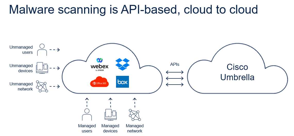
CASB – Cloud Access Security Broker
Definition of CASB – Providing a central location for policy and governance concurrently across multiple cloud servises and granular visibility into and control over user activites and sensitive data from both inside and outside the enterprise permieter, including cloud-to-cloud access. What the hell does this actually mean?
Umbrella provides CASB in two ways:
Inline/Real time which means that traffic to the SaaS provider is intercepted, and scanning/policies are applied before it reaches the SaaS provider.
Out of band which essentially is SaaS API and this means that when activity goes from the user directly to the SaaS provider then then through an API connection. The CASB applies the policy to provide visibility, protects the user or control their activity.
Cloud malware scans data at rest (Data at rest is data that is not actively moving from device to device or network to network such as data stored on a hard drive, laptop, flash drive, or archived/stored in some other way.) in the SaaS service. Cloud to Cloud scanning
Real Time DLP scans outbound web traffic inline through our secure web gateway proxy for all cloud destinations, whereas SaaS API DLP scans outbound web traffic out-of-band while it’s at rest in the cloud, via restful API, instead of it going through the secure web gateway proxy, but with near real-time enforcement.
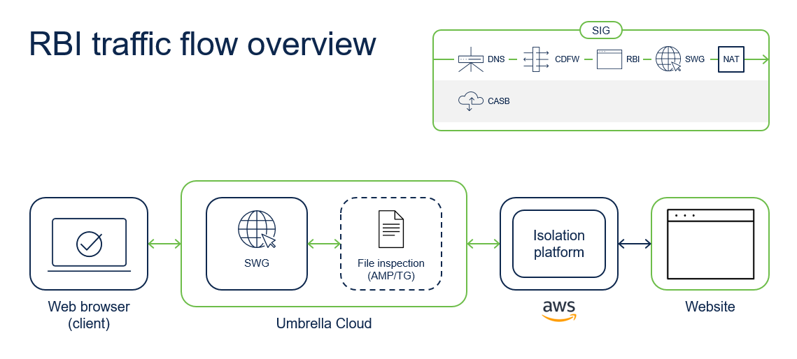
Remote Browser Isolation
Typically if you need to access a potental risky site or uncategorised URL for a legitimate reason, RBI can help. RBI isolates web traffic from the user device and the threat in a air gap enironment. Air gap meaning is the specific device or network is isolated behind closed doors essentially.
RBI frees you from the need to know what’s bad or not. It lets users go where they need, without the risk of malware that hasn’t been detected yet. With RBI, customers can stop browser-based attacks, and users can get a safe browsing experience without sacrificing productivity. IT teams will spend less time dealing with resolving access issues. And since it’s cloud-delivered, RBI is easy to scale on demand, and works with all devices, browsers, and operating systems.
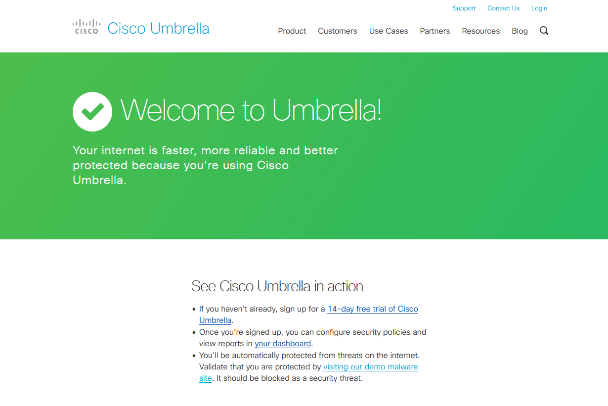
Configuring Basic Umbrella
First of all you would need to change the DNS to Umbrellas DNS – I am using my laptop as an example and pointing the DNS Server
208.67.222.222
208.67.220.220
Then test to make sure it has pointed to Umbrella using the URL https://welcome.umbrella.com/
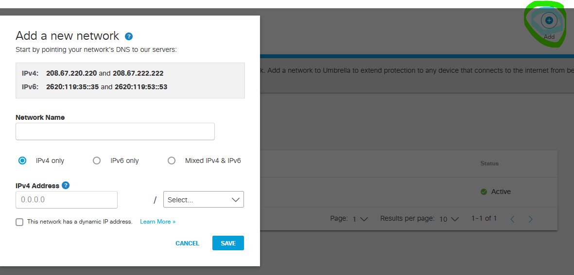
When you login to Cisco Umbrella you will need to create a Network. A Network is what identifies the network or device you are protecting. In this example I chose my laptop which is NAT’d behind a Public Dynamic IP. Now you maybe wondering if it is Dynamic as not every Business may have a Static IP, then how would it work when IPs will change?
With umbrella, you can install a lightweight agent which will continuously poll with umbrella so should there be an IP change it will sync with your Umbrella Network.
Click the add button then you can enter your Public IP and as I can only afford a single IP, I will choose /32.
Next, go to DNS Policies
Click to add a new Policy
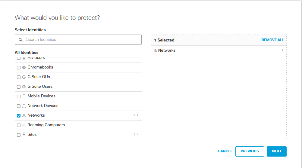
Click Next
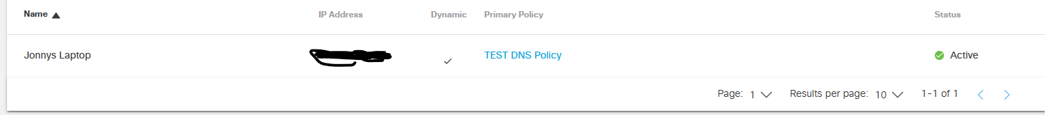
Scroll down until you see Networks, you will notice there is a 1 next to it. Remember on the earlier steps we had to add the Networks which was my laptop I wanted to protect?
Next again
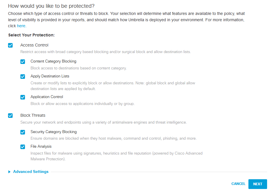
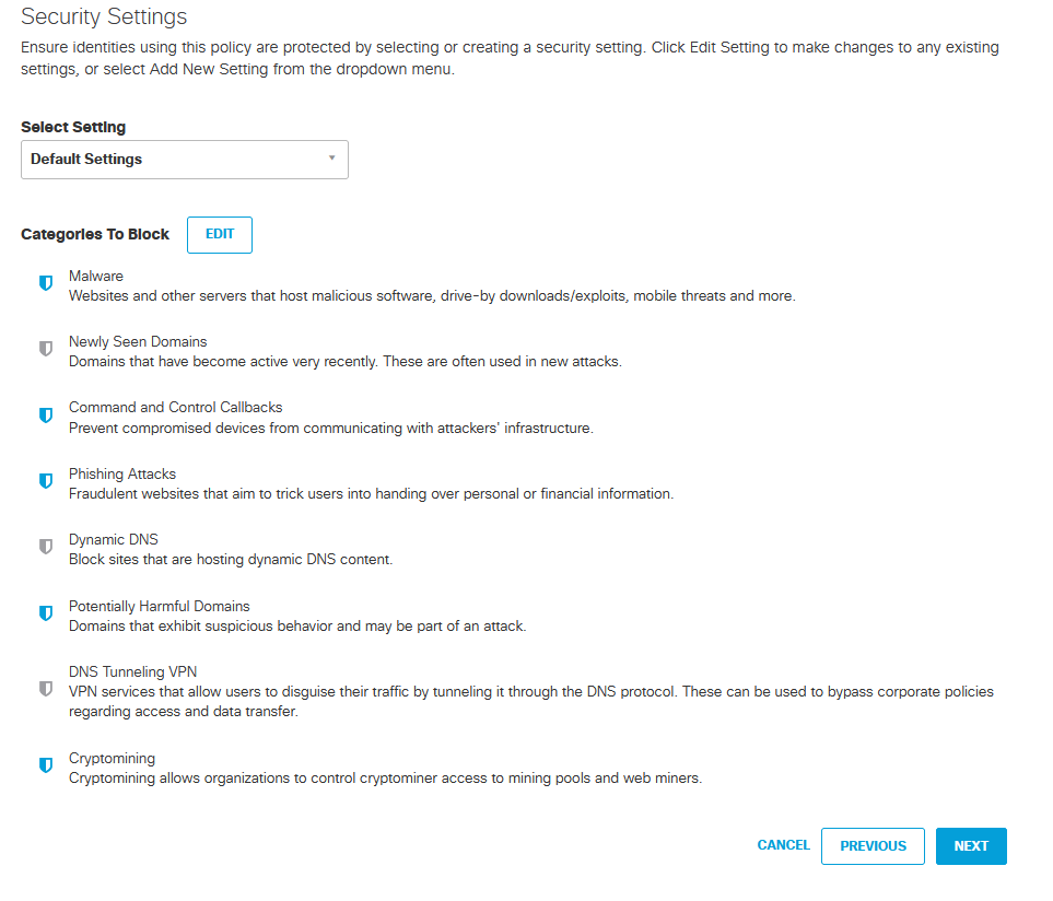
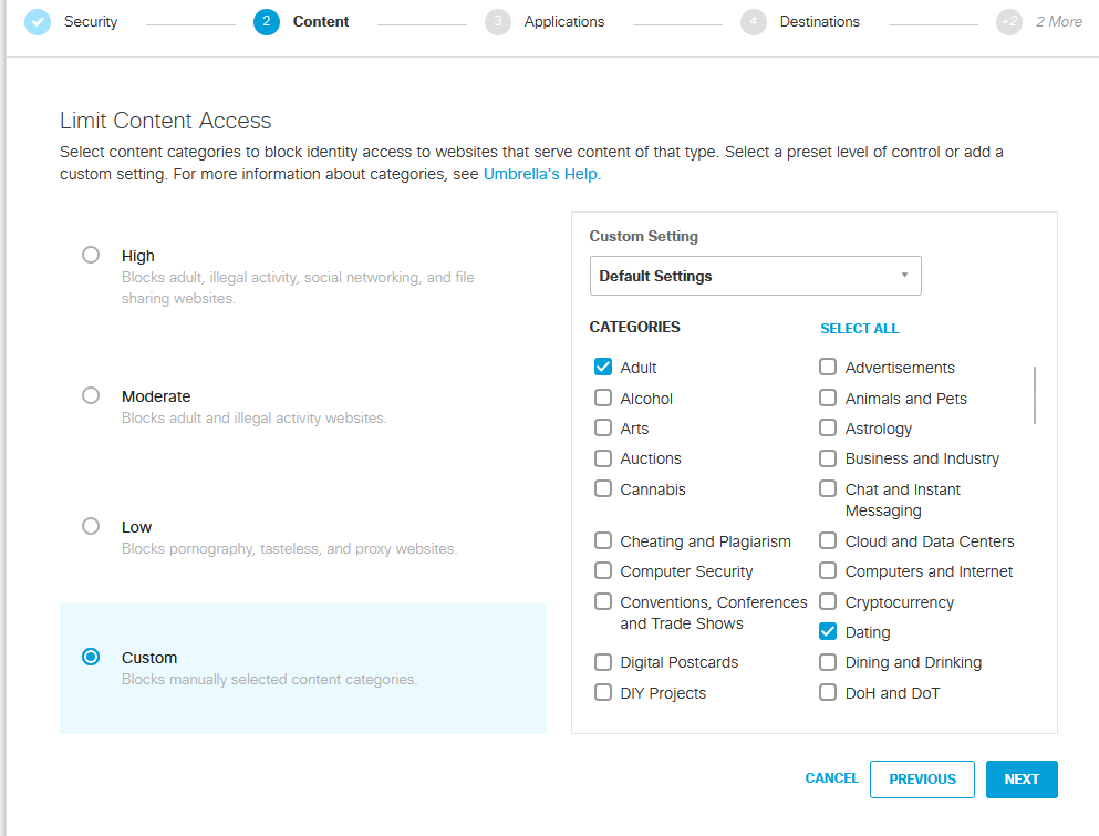
This is where you can block the types of content.
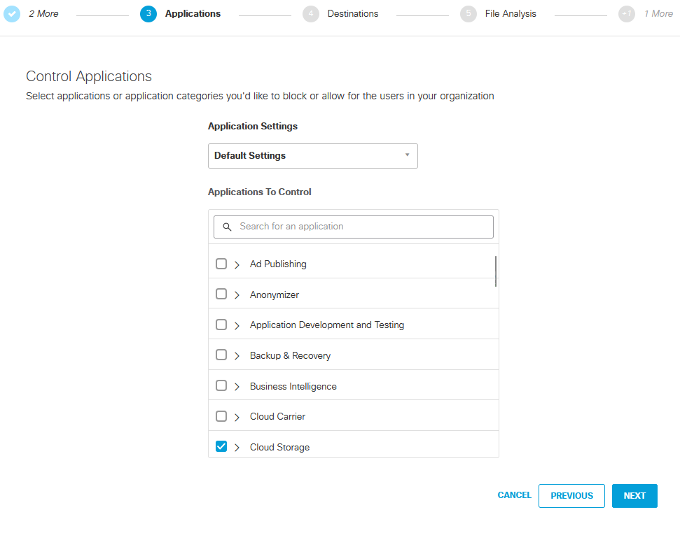
And click next if you do not want to block L7 Applications
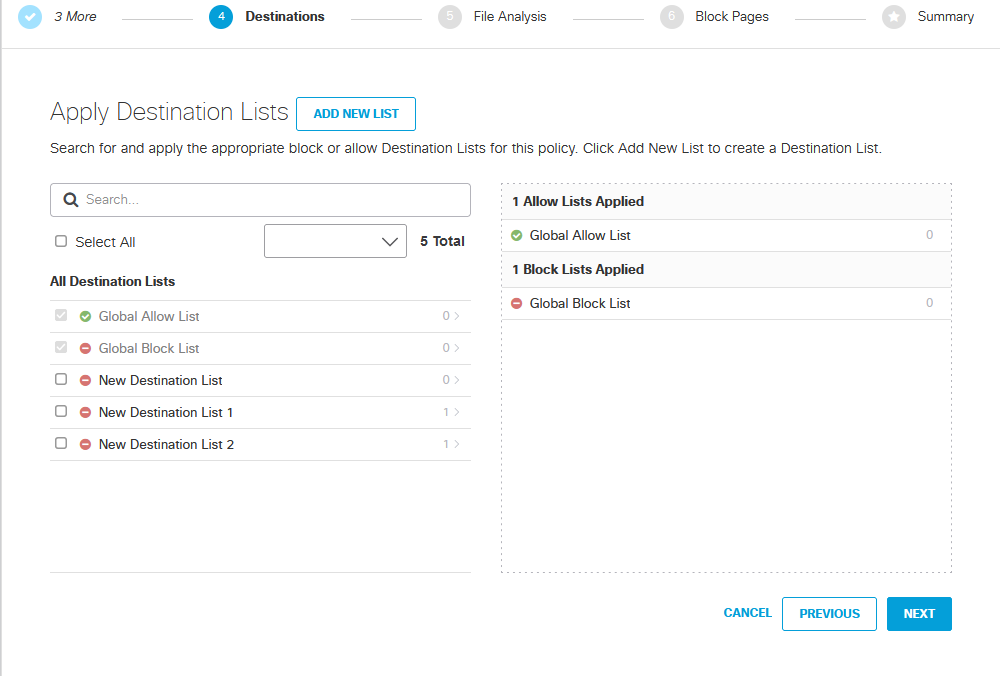
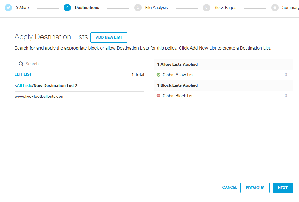
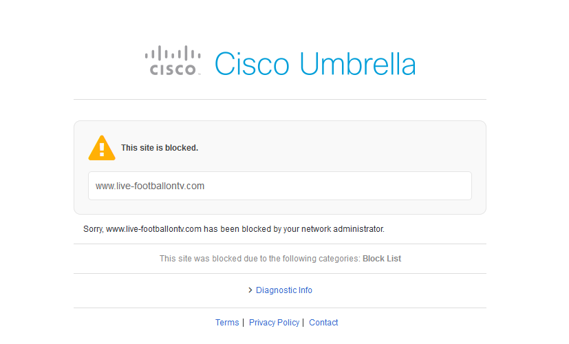
This is where you can block URLs which in this example I will be configuring to block a specific URL.
I have added a new list called New Destination List 2 and it contain the URL www.live-footballontv.com
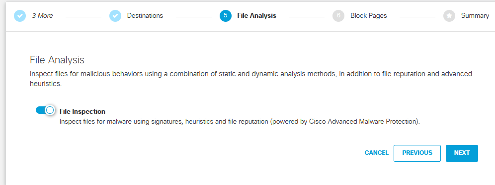
If you wanted file inspection it is on by default then click next.
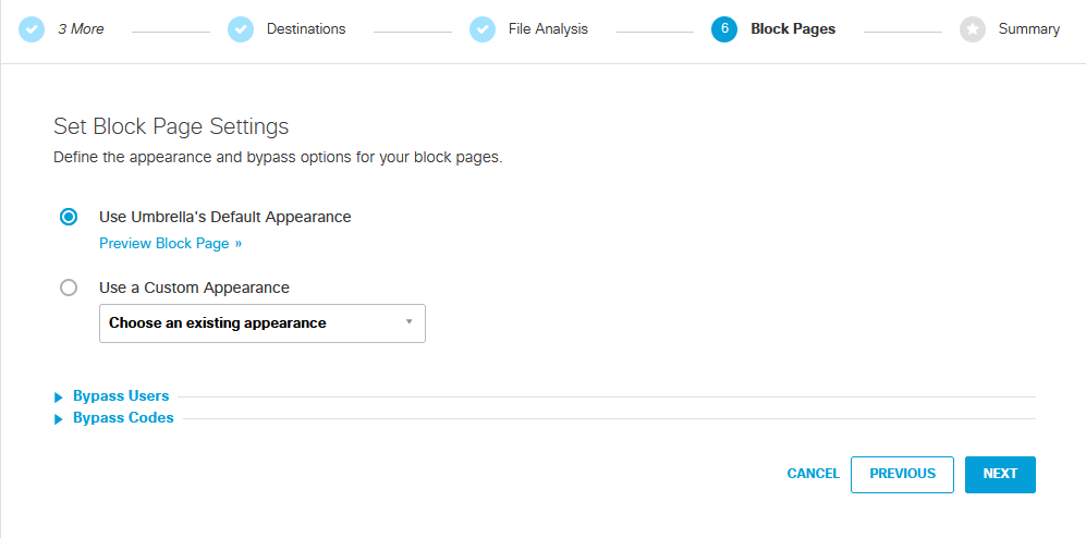
Now, if the end user does access the blocked URL I configured before you can choose which display appearance it provides to the user.
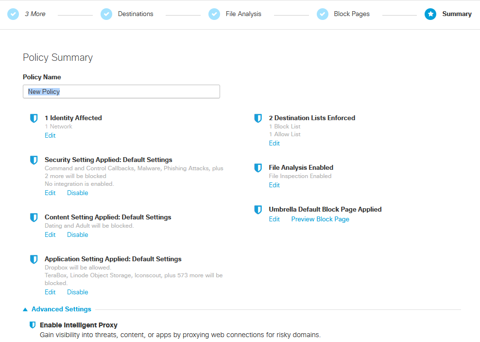
And finally, you can choose to name your new Policy.
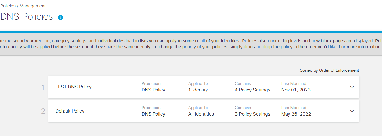
As you can see my new Policy is complete. Let’s try the URL I have specifically blocked and see Umbrella work its magic!
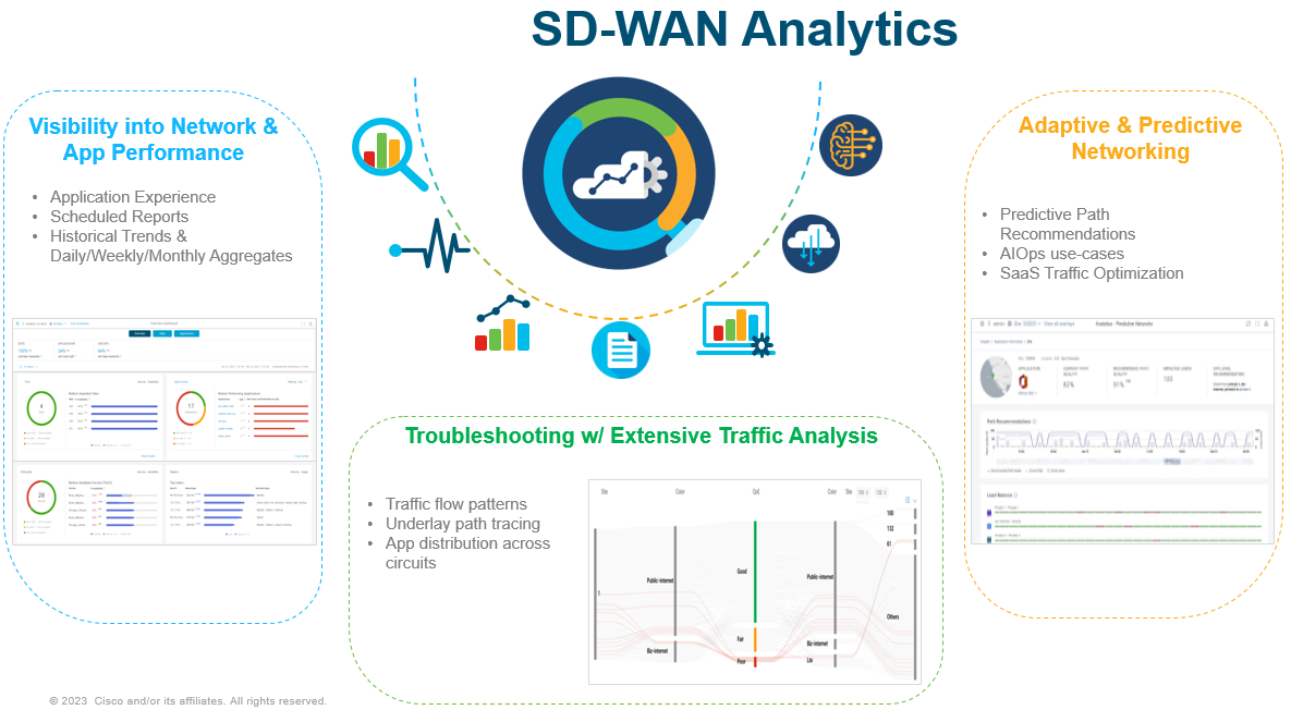
As more and more Applications and workloads are being shifted to the Cloud, Enterprises are tasked with maintaining and operating these applications.
This is how Cisco SD-WAN Analytics with SD-WAN can help with increased visibility and insights for better control and troubleshooting issues a lot faster when they occur.
SD-WAN Analytics is broken into three pillars:
Visibility
Troubleshooting
Predictive Networking
Edge routers send their data to SD-WAN Manager which in turn uses secure APIs to then transferred data to Analytics, Analytics is hoses in AWS Cloud.
Visibility
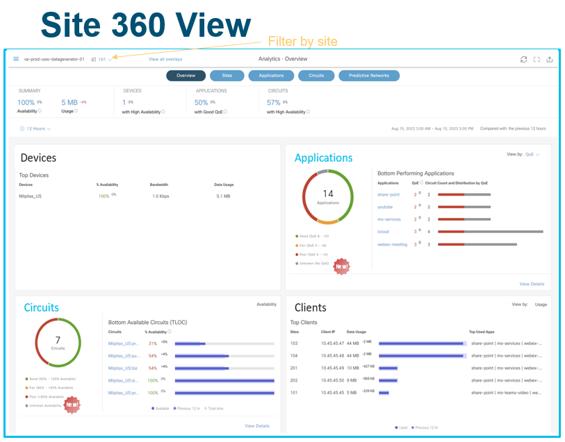
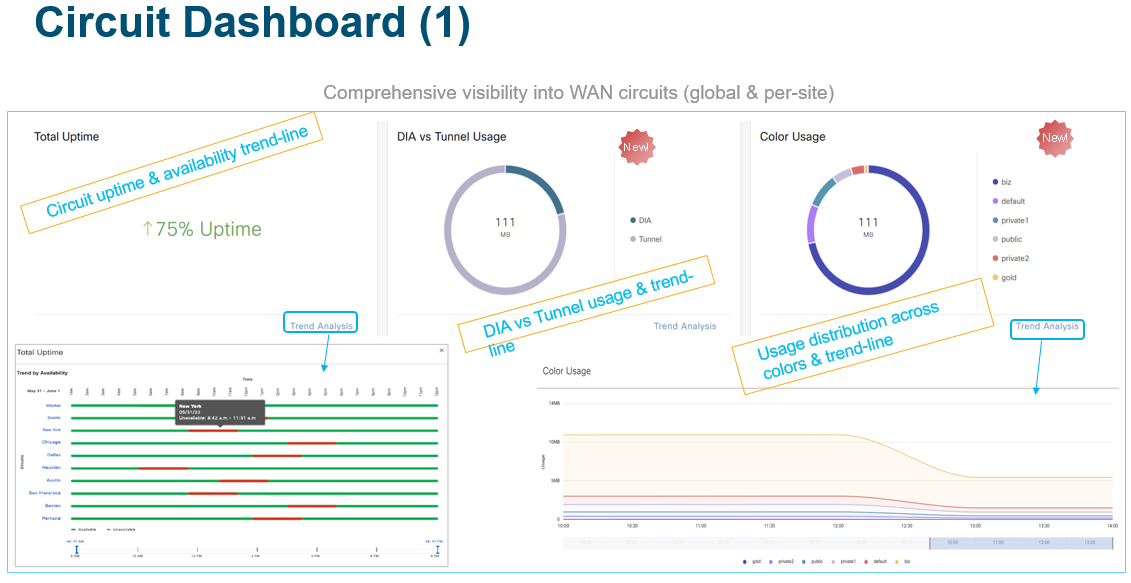
Summary Dashboard is the landing page/homepage when you login to Manager, this provides a quick snapshot of your entire application and network. This allows Enterprises to quickly access the health of their overall network and applications.
It is organised into 4 key widgets:
Applications
Sites
Circuits
Users
Each widget gives you the capability and displays the change in metric compared to the previous time period. The time period can be from 12 hours to 1 month. You can also choose to view data for up to 7 days in the past 3 months.
The summary image above allows the user to view a specific site instead of the whole of SD-WAN network. This allows the user to see what applications are being used, circuit health and the clients on the Service side VPN.
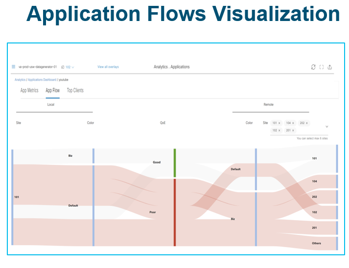
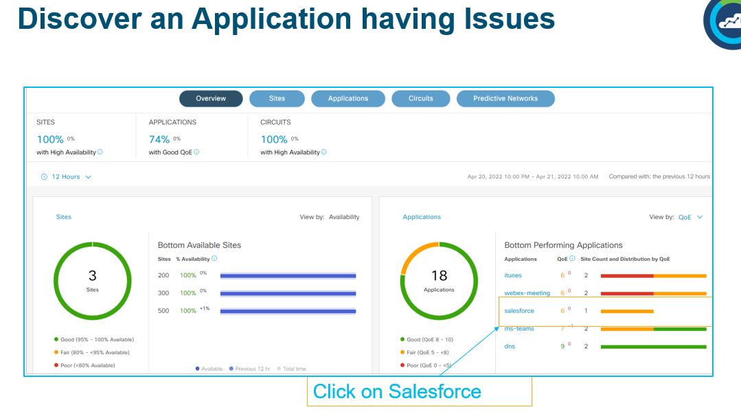
On the Applications Dashboard allows the user to view the application QoE with a score based on how well the application is performing.
1 – Application summary by QoE with health score and usage through the GUI, usage stats for Apps.
2 – Get an aggregated view into how a group of similar applications is performing.
3 – trending applications that is showing a drop or rise in QoE.
4 – Compare and analyse usage QoE across different apps over time
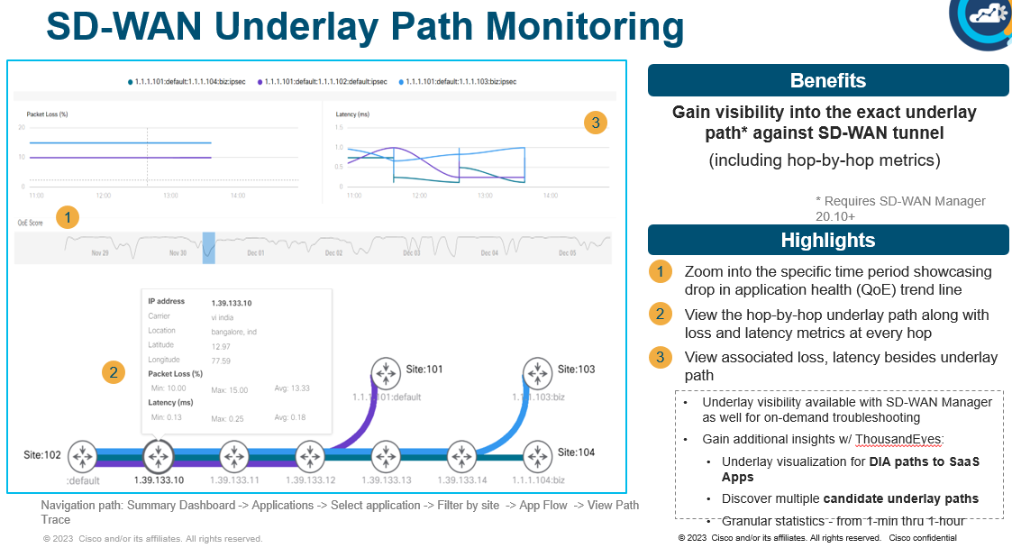
Visualisation diagram shows what are the top used remote sites for a specific application for a specific site. This also offers how traffic is being distributed by QoE and what Colours (Transport) is being used for that application.
Troubleshooting
On the Dashboard Overview – you can view the bottom performing Applications. using SalesForce as an example.
To gain further insights, you can utilise the SD-WAN Underlay Visibility feature that allows you to drill all the way down to the SD-WAN tunnel’s underlay path and view metrics such as loss and latency on a hop by hop basis. This capability will also be available on SD-WAN Manager on an on-demand basis while SD-WAN Analytics will offer a historical view of your underlay path.
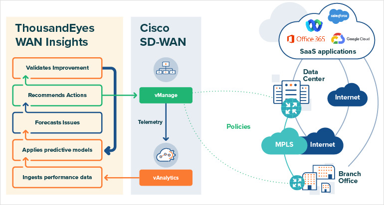
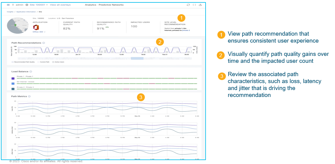
Predictive Insights/WAN Insights
This is a Cisco Product which is a close collaboration between SD-WAN Anaylytics and ThousandEyes. This is available on v20.12.x
WAN Insights predicts path recommendation features, monitors network path performance over the historical time (minimum 24 hours), which is then applied with predictive daya modelling to it. Essentially forcasts likely issues in the future and makes appropriate recommendations for alternate network paths of applications.
Enterprises can then take advantage of these recommendations to fine-tune their SD-WAN policies to avoid any future performance issues which results in optimised application experience.
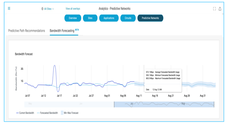
Forecase future WAN Bandwidth needs
Using Artificial Inteligence and Machine Learning, you can forecase bandwidth usage. Dotted line is the forecasted bandwidth for a circuit, Solid line is the actual bandwidth of a circuit. This will be useful especially for MSPs or ISPs that is providing transports as well as SD-WAN managed Service.
I have already written a Blog about EAAR (http://jaychou.co.uk/?p=613) – This section is based on standard AAR.
A better example to understand AAR is having a scenario where there are multiple Transports such as Biz-Internet, Internet and LTE. Should there be an issue with one of the Transports which will impact the user experience. With AAR, you create a threshold for a specific Application so should the transport not meet SLA then it will switch to another Transport (fastest is 10minutes unless using EAAR which is 10s).
AAR is measured against Latency/Jitter/Loss, when the user configures the Application Aware Routing Policy then you can set the threshold before the transport switches over. This ensures the SLA is compliant through the SD-WAN fabric.
BFD is used for AAR, which has two timers:
BFD timer on Transport Tunnels, this is used to define the BFD frequency – such as BFD colour, hello-interval in milliseconds and the multipler in terms of frequency it happens.
BFD timer for AAR which defines often BFD polls all data plane tunnel stratistics and is used to collect packet latency, loss, and jitter.
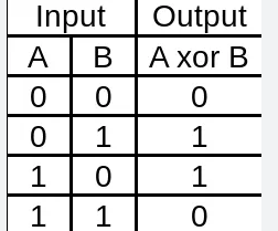
Forward Error Correction (FEC)
FEC uses the XOR cipher. If the Cipher is the same then no change has been made. An example of XOR operation below:
This helps to understand how FEC is operated, XOR allows FEC to create a parity packet which then reconstructs the lost packet.
FEC helps the following :
Protects against packet loss
Operates per-tunnel
Supports multiple transports
Can be invoked as and when
Applied within the Data Policy
FEC can only reconstruct 1 packet out of 4.
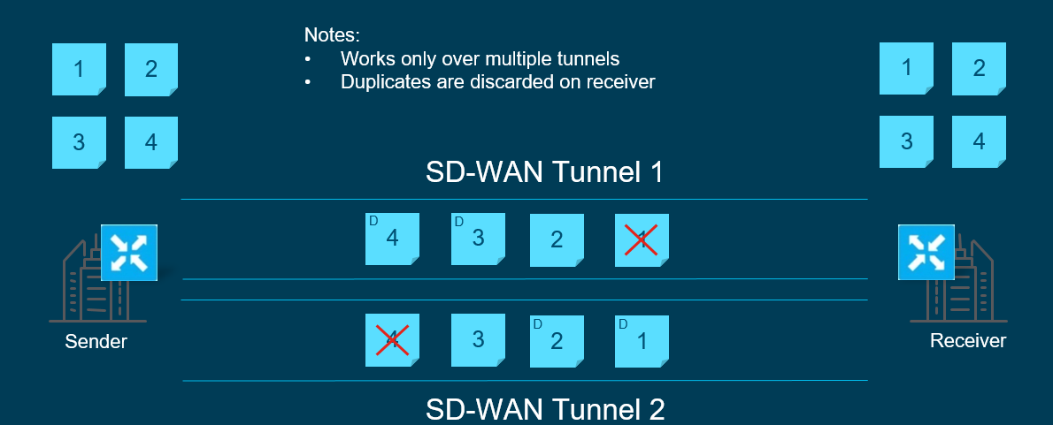
Packet Duplication
As the name suggests, this allows duplcating packets for critical traffic/application such as Credit or ATM transactions and sending the duplicated path over a second path.
This can work when there is little or limited of Critical traffic compared to the capacity of the network. If there is multiple circuits then SD-WAN will choose the best transport. Best as in the least amount of packet loss to replicate the packets to.
When transferring, duplicate the packets of the primary tunnel and send simultanousely, the secondary/duplicated tunnel is chosen based on MTU. Duplication happens only if the secondary tunnel MTU is greater or equal to that of first to avoid fragmentation. When the receiving router receives the first packet to the LAN whether it is duplicate or original it will drop the other one.
QoS
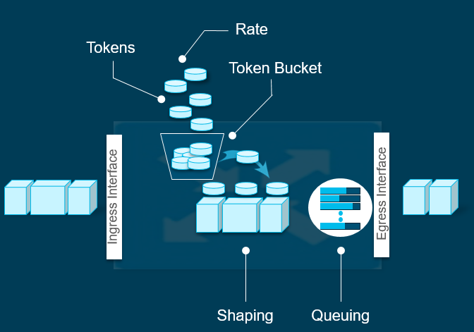
Queuing
Is used when Shaping is being utilised. This allows the packets to sit in a queue waiting to be sent in the egress interface. Uses Weighted Round-Robin, when the queue gets dropped it uses Random Early Discard.
Shaping
Is used when you do not want to drop the packet if there is a queue and exceeded the configured Shaper rate. Essentially if there are no more tokens in the bucket it will be placed in a queue. The queued packets will operate in Weighted Round-Robin. This is not supported on Sub-interfaces.
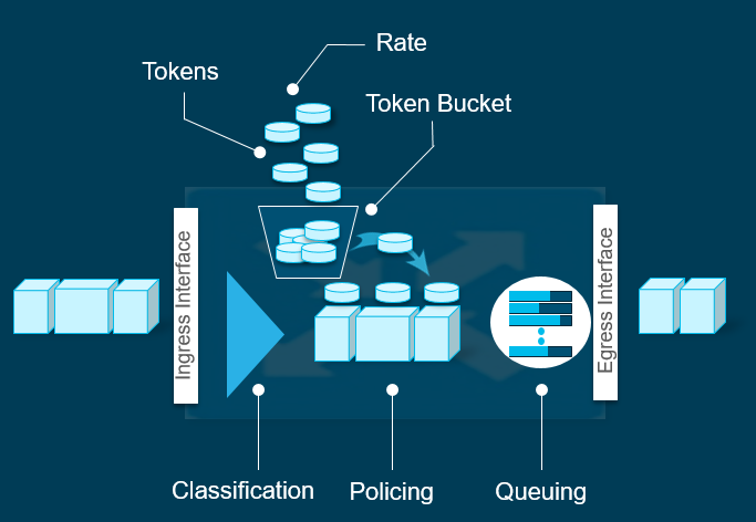
Policing
Is used if you want to completely drop the traffic if does not conform the policer rate.
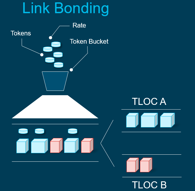
Link Bonding
You can bond both transport links together – this essentially means it will be per packet load sharing, with the receiving host ordering the packets if packets are being send out of order.
None-conforming traffic will spill over to a different circuit.
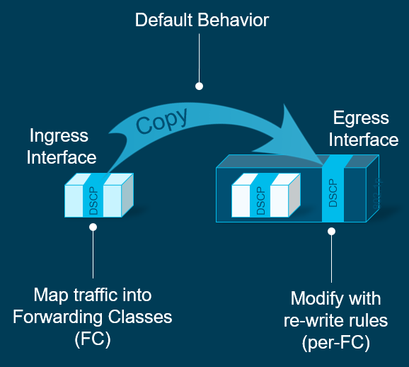
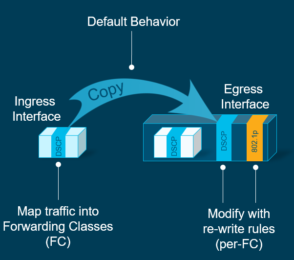
DSCP Marking an Remarking
DSCP operates on Layer 3, so as a packet is being mapped into a forwarding class, you can modify this to another DSCP rule.
COS (802.1p) Marking and Re-marking
You can remark COS (Layer 2) frames.
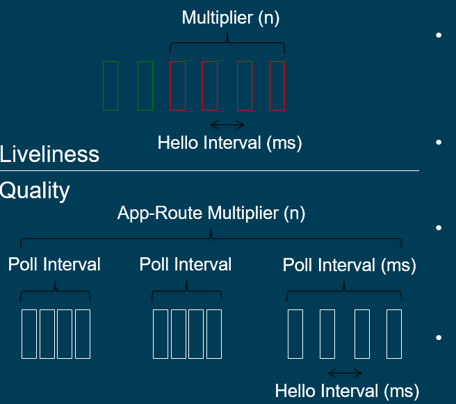
Path Quality and Liveliness Detection
Each WAN Edge router sends BFD Hello packets for path quality and liveliness detection, the packets will be echoed back by the receiving router. Using Hello interval and multiplier will determine how many BFD packets need to be lost in order to declare whether the IPsec tunnel is down.
The number of hello intervals that fit inside the Poll interval determins the number of BFD packets considered for establising poll interval average path quality.
The App Route multuplier determines the number of poll intervals for establishing the ocerall average path quality.
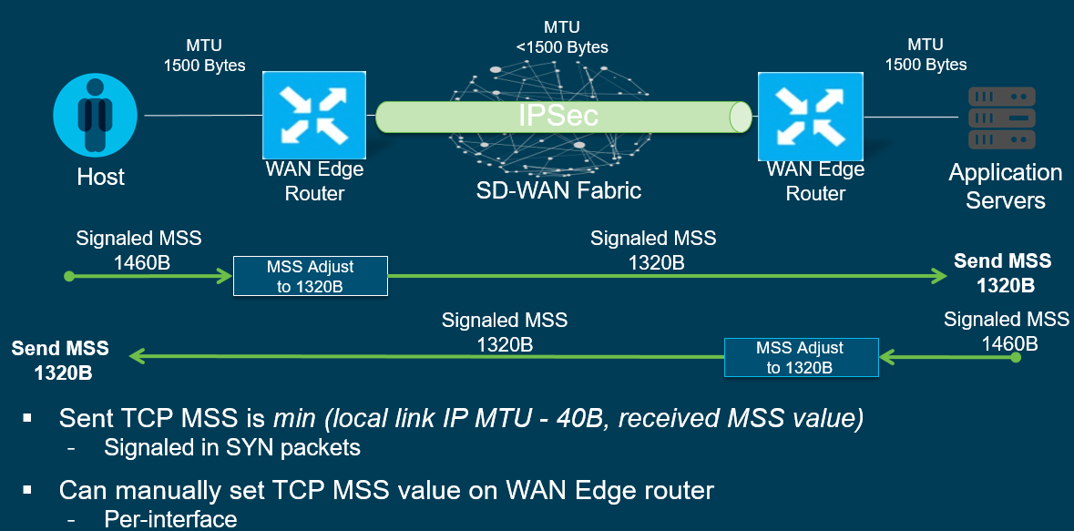
TCP MSS Adjust
This is used to help the need in fragmentation of packets, Routers on the WAN edge will signal the appropriate MTU based on the host/application on the LAN. This in turn will be forwarded to the receiving router in terms of the appropriate MTU it needs to be.
Per-Tunnel QoS support on SD-WAN
This allows the site to dynamically adjust the sending rate of its traffic to acomodate lower bandwidth circuits at remote sites.
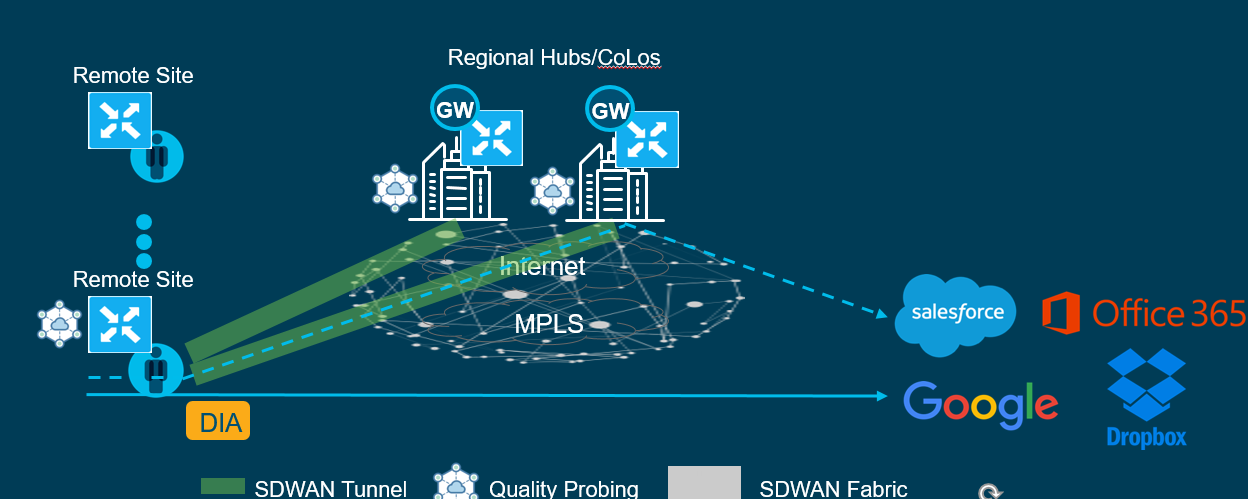
Cloud onRamp for SaaS
Cloud on Ramp allows quality probing towards popular SaaS Application, the WAN Edge router chooses the best porforming path towards the popular Saas Applications.
CoR works by using the following 3 components:
DNS Resolution
Performance Visibility
Path Selection
An example is if you had two DIA transports to the SaaS application, CoR monitors the edge to the SaaS application. This in turn then picks the best porforming metrics such as loss and delay.
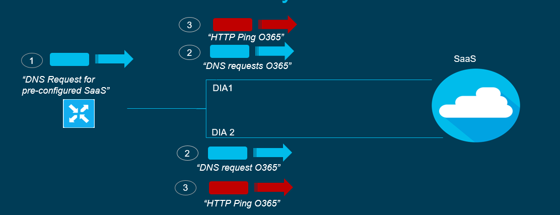
Perfomance Visiibilty works by the WAN edge reuesting DNS in VPN0 and sends a DNS reuest for the pre-configured SaaS application.
DNS requests are duplicated and sent to all transports to get the application server address.
HTTP pings are sent to the application such as SalesForce servers on both the DIA links for performance measurements.
The results and score is measured from 0-10 with 10 being the best.
0-5 RED
5-8 Yellow
8-10 Green
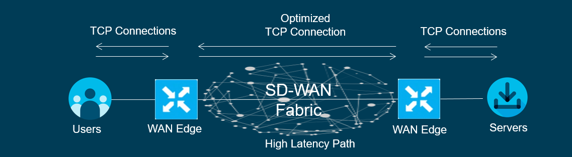
TCP Optimisation
TCP optimisation fine tunes the processing of TCP traffic which in turn decreases the round-trip latency to improve throughput.
An example is if you are using a high latency link like a satelite transport attempting to connect to a SaaS based or Server, the TCP handshake is formed from Client to the Router. This TCP connection will be terminated and in turn the router will then form another TCP handshake with the remote router. This TCP handshake from WAN Edge to WAN Edge will be cached. The remote router will form a TCP handshake with the Server.
SD-AVC – Advanced Visibilility Control
Essentially using NBAR2 to classify and regonise applications, it uses DPI plus different techniques such as:
Currently with SD-WAN deployments, it will be delivered in a ‘flat’ layer network where all Edge routers connects to each other regardless of where location and country.
An example with diagram below is that you could have multiple sites across Europe as well as sites in Asia. Both regions will be connected to wherever the Controller and Manager is.
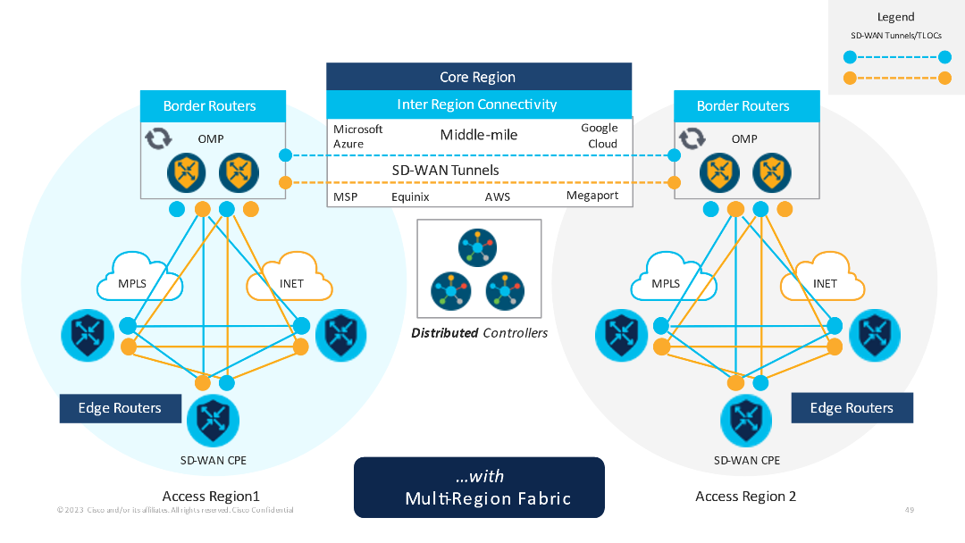
Multi-Region Fabric
Introducing MRF, in how this works. The first iteration of MRF is introduced in v20.7.x.
With MRF, we have introduced new terminlogies and roles. To begin, we have:
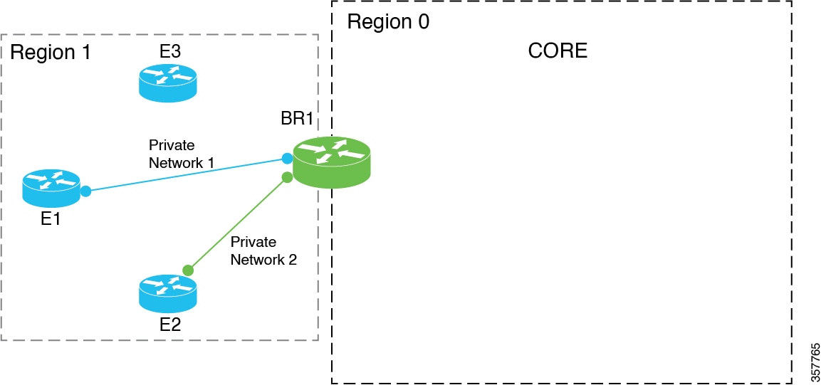
Border Routers – This is the edge of each region where it connects to the backbone of the network/middle mile. It is responsible for the routes within the region itself.
Core Region – This is the middle mile where you are expected to have high speed back bone network whether you are traversing the Cloud or just huge network pipes.
Edge Routers – Sites with vEdge or cEdge devices.
Intra-region – Sites that connect and send traffic within the same region.
Inter-region – Sites from different regions and sends traffic to the Border router which in turn sends across to the backbone and to another region.
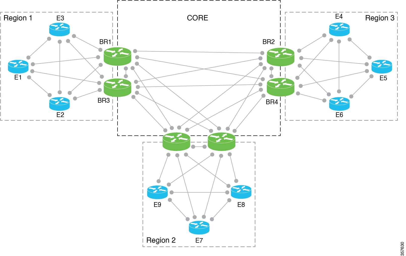
Another example/simplified diagram of MRF below. MRF also introduces region numbers. The Core region will always be 0. Other regions will need to connect to the Core region with Border Routers. You can compare this with OSPF Areas.
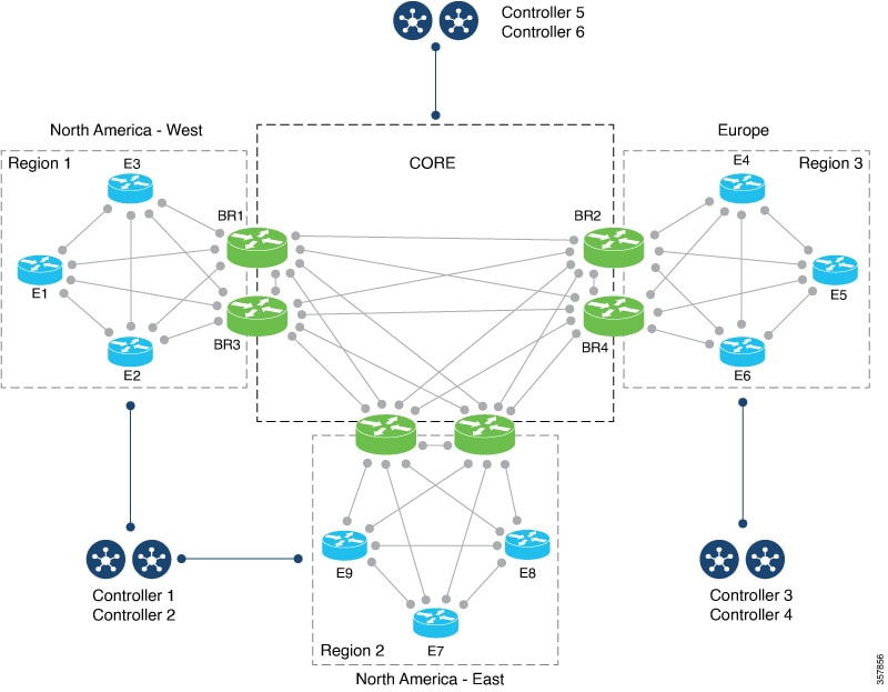
Another new addition is introducing Cisco Controllers (vSmarts) to each region, traditionally you would utilise either 1 or a cluster of vSmarts to serve the whole SD-WAN network. WIth MRF, each region will have its own Controller(s) and will serve only for the region it belongs to.
Benefits of MRF
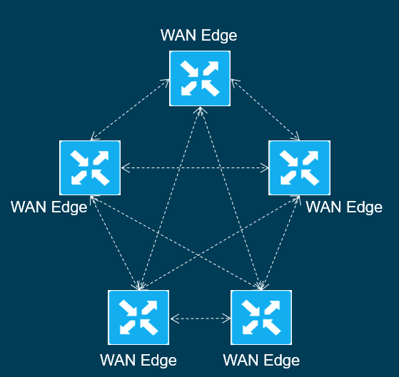
Current SD-WAN acts as a flat overlay model, essentially site to site tunnels are connected to each other.
Most use case is sufficient for flat overlay model, however with larger Enpterprise Busineses that operate globally, this will introduce some limitations such as:
OMP Limitations
Config Complexity
Control Policy Complexity
FLat overlay does not scale after a certain number of tunnels
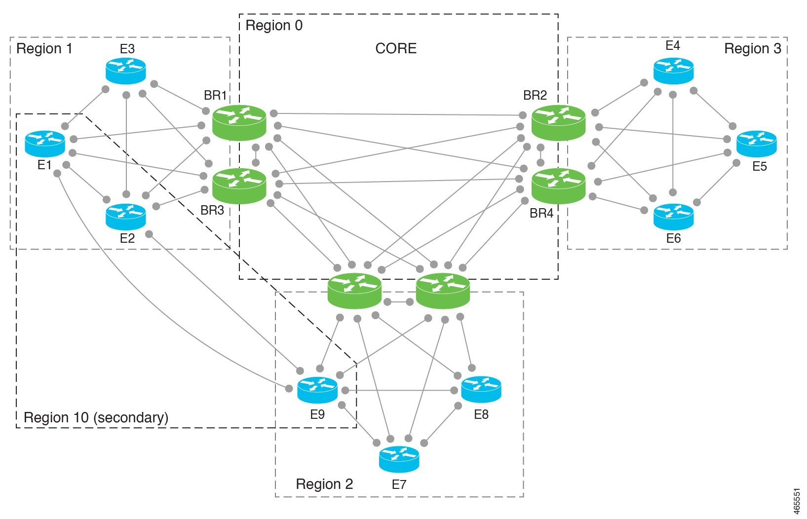
Secondary Regions
This feature was released in v20.8.1 and 17.8.1a for IOS-XE.
With MRF we have introduced to basic multi-regions, now with Secondary region you have the ability to connect two Edge or more sites in different regions to one Secondary region.
Example above shows that three edge devices can connect directly or form a single secondary region, with OMP it will always choose the direct path first, therefore it may not allow the route to be installed on the forwarding table via the Border router path. You can disable the comparison of number of hops so it will become ECMP.
Secondary Region allows:
Load balancing using Primary and Secondary region paths.
Directing specific Applications to use the Secondary Path which could have a faster perfomance underlay like a Lease line at 1Gbps.
Caveats of Secondary Region
Only to Edge routers not Border routers
A router can only belong to one Seconday region only.
Controller cannot be part of any primary or access regions , recommended to utilise a separate Controller for a Secondary Region.
Transport Gateway
This feature was released in v20.8.1 and 17.8.1a for IOS-XE.
Transport Gateway is used if within a region and Edge routers do not have a direct connection to each other. Transport Gateway can help to facilitate this by essentially bridging the two networks together.
Transport Gateway only works for IOS-XE.
Router Affinity
This feature was released in v20.8.1 and 17.8.1a for IOS-XE.
If you have multiple exit paths, you can advertise to the Border Routers to prefer one path over another.
For example with the above, DC is advertising the two subnets. With the two BR’s you could set BR1 to prefer ER1 and should ER1 fail then failover to ER2. For BR2 this is vice versa where it will prefer ER2 then ER1.
Since the release of version 20.12.x, Cisco has renames the controllers to the following:
vManage – Manager
vSmart – Controller
vBond – Validator
vAnalytics – Analytics
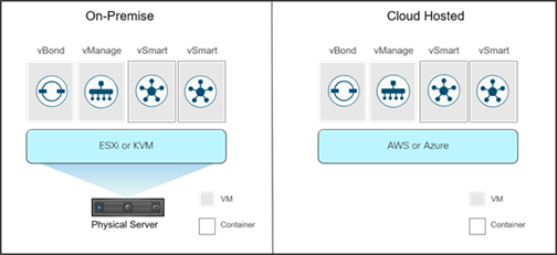
On prem SD-WAN Design Deployment
With On Prem you can deploy using ESXi or KVM and as VM’s or Containers.
max-control-connections 0 command is used if you are using a transport which cannot obtain a control plane connection back to Manager. So in other words you will not be communicating to Manager using that transport, but with this instance you will communicate via control plane using another transport like Internet.
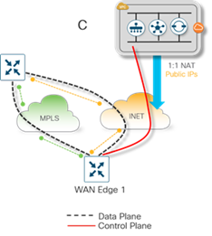
The Manager and Controller controllers use a public color on their tunnel interfaces. This ensures they will always use public IP addresses to communicate with any WAN Edge devices. There is no concept of color on the Validator interface.
It is a requirement for Validator to communicate to Controller and Manager through their public addresses so the Validator can learn those IP addresses and pass those public IP addresses to the WAN Edge devices wanting to connect into the overlay.
Manager and Controller communicate to each other via their NATed public IP addresses. This is due to their public color configuration and their site ID configurations being different. If their site IDs were equal, they would be communicating via their private IP addresses, bypassing the gateway for that communication.
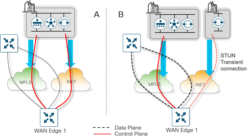
On-Premise Controller Deployment
STUN server acts like a proxy where if you had the controllers hosted privately in a MPLS for example environment and other branch devices are sitting behind Internet transport you could setup another Validator on the Internet which will redirect the Private IP of the controllers. This is useful when you have a new device which is being onboarded to SD-WAN and needs to connect back to the Controllers in a Private network such as MPLS.
Controller Redundancy/High Availability
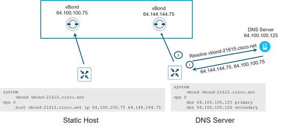
Validator
Validator redundancy is done by using FQDN and A records, is it recommended to spin Validator in different geographic regions and data centres. This ensures at least one Validator will be available for registering to join the overlay.
Always recommended to use Validator in FQDN instead of IP addressing, in DNS there will be multiple IP’s attached to the FQDN of the Validator it will go through each IP until a successful connection is formed.
Controller
It is recommended to use Controller controllers in different geographic regions if managed from the cloud or in different geographic locations/data centers if deployed on-premise to maintain proper redundancy.
By default, a WAN Edge router will connect to two Controller controllers over each transport. If one of the Controller controllers fails, the other Controller controller seamlessly takes over handling the control plane of the network.
Controller controllers maintain a full mesh of DTLS/TLS connections to each other, over which a full mesh of OMP sessions are formed. Over the OMP sessions, the Controller controllers stay synchronized by exchanging routes, TLOCs, policies, services, and encryption keys.
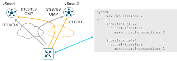
By default each Wan edge can make two control connections in VPN 0.
Controller Affinity
Essentially you can group the Controllers into groups and allow failover, however best practice is to place Controllers in different Regions/DCs with the WAN edge connecting to one Controller in one group and another Controller in another group/DC.
The following is configured on the WAN Edge router:
● max-omp-sessions 2: the WAN Edge device can attach up to 2 different Controller controllers (there is one OMP session established per Controller, regardless of the number of DTLS/TLS sessions formed between two devices).
● max-control-connections 2: the WAN Edge device can attach to two Controller controllers per TLOC.
● controller-group-list 1 2 4: indicates which control groups the WAN Edge router belongs to, in order of preference. The router is able to connect to controllers that are in the same controller group. The WAN Edge router attempts to attach to all controller groups not explicitly excluded based on the current state of the controller and the WAN Edge configuration session limits. In this example, the router first attempts to connect to a Controller controller in group 1 and then one in group 2 in each transport.
● exclude-controller-group-list 3: indicates to never attach to controller-group-id 3.
If a Controller controller in controller-group-id 1 becomes unavailable, the WAN Edge router will attempt to connect to another Controller controller in controller-group-id 1. If controller-group-id’s 1 and 2 are both unavailable, the WAN Edge router will attempt to connect to another available group in the controller-group-list (4) excluding controller-group-id 3, or any other group defined by the exclude-controller-group-id command. If no other controller groups are listed in the controller-group-list, the router loses connection to the overlay.
Manager Network Management System (NMS)
All Manager in a cluster will operate in Active mode.
It provides redundancy against a single Manager failure. But not a cluster level.
Clustering across Geographic locations is not recommended as it requires 4ms or less latency. So members of clusters should reside at the same site.
Redundancy is achieved through Active and backup in standby mode.
General rule of thumb is less than 2000 routers then one Manager in Active aand another Manager in standby.
If more than 2000 routers then Manager as cluster and another cluster in standby via two different geographic locations.
Depending on the network, application visibility and statistics can be CPU intensive on Manager, thus reducing the number of WAN Edge routers supported by a single Manager.
To prefer a specific tunnel interface to use to connect to Manager, use a higher preference value. Try to use the highest bandwidth link for the Manager connection and avoid cellular interfaces if possible. A zero value indicates that tunnel interface should never connect to Manager. At least one tunnel interface must have a non-zero value.
Manager clustering
When clustering other than the two interfaces for VPN 0 and 512 you need a third interface to connect and sync to other Manager servers within the cluster – least 1Gb and recommended 10Gbs (4ms or less)
If deploying on ESXi use VMNET 4 adapter as it supports 10Gbps.
In a cluser the config and statitics should be run on at least 3Managers and each service must run/support odd number of routers to ensure data consistency during write operations.
Disaster Recovery
Validator and Controller are stateless so snapshots can be made before any maintenance or config changes or their config can be copied and saved if running in CLI mode.
Manager is stateful therefore backup cannot be deployed in active mode, snapshots should be taken and the database backed up regularly.
When you have active and backup in two different DCs you will have Validator and Controller too in both DC’s so the Manager will establish with whichever active to respond first of Validator and Controller.
Administrator-triggered failover (Manager cluster) (recommended)– Starting in the 19.2 version of Manager code, the administrator-triggered disaster recovery switchover option can be configured. Data is replicated automatically between the primary and secondary Manager clusters. When needed, a switchover is manually performed to the secondary Manager cluster.
Controller Deployment Examples
Minimal controller design (<= 2000 devices) – this design contains 1 active and 1 standby Manager, 2 Validator orchestrators, and 2 Controller controller, split between two different regions.
contains 3 Validators, 3 Controllers, and 1 active and 1 standby Manager. Controller affinity is used so WAN Edge devices connect to the Controllers in the two closest geographical areas (North America and Europe, or Europe and Asia as examples).
contains 1 active and 1 standby Manager cluster, each with 3 Manager instances. One Manager in the cluster could be disabled but the rest of the cluster could support the WAN Edge devices. It also includes 4 Validator orchestrators, 4 Controller controllers, split between multiple sites within a region or globally. Controller affinity is used to so WAN Edge devices can connect to Controller controllers in the two closes geographical areas.
In version 20.12, Catalyst SD-WAN created Enhanced Application Aware-Routing. The issue with standard AAR (Application Aware-Routing) is that it uses BFD tunnel performance measurements, this can take from 10minutes – 60minutes for convergance times to detect SLA breaches and failover. If you start configuirng the performance timer then this could create false positives.
AAR is measured based on:
Loss – The number of BFD echoes that failed to reply
Latency – How long it takes to recieve the BFD echo and Hello (RTT)
Jitter – Measuring the delay of the packet arrival times, also measures irregularity of the packet as it is being transmitted and received.
With EAAR, improvements have been made which are the following:
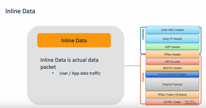
Performance metrics (Loss/Latency/Jitter) is improved by introducing Inline Data. Inline data is the traffic that is being inspected at the edge of the network. Instead of traffic being routed to a central location for analysis and security checks, Inline data is being inspected and forward/data place decisions is being made at the edge. Loss is being measured with two differences. Loss is being measurements uses Per queue Adaptive-QoS Metrics which includes Per Queue path loss – this means it will be able to differentiate whether it is local loss or loss on the WAN circuit. Latency is RTT with Patented method where we insert metadata for measurements. Wheres Jitter is measured Unidirectional
Peformance poll-interval has decreased to minimum of 10s, as mentioned above standard AAR is minimum of 10minutes. Therefore should there be a breach of threshold then it will only take a matter of seconds instead of minutes.
SLA Dampening – Same principle as BGP route dampening. Essentially is the SLA is being breached back and forth instead of re-adding the transport back it will need to stabilise first before being added back. This helps stability and prevents disruptions.
Caveats
EAAR is available on IOS-XE 17.12.1a. If one has EAAR disabled or an older version then it will not work and will default to standard AAR.
If both versions is 17.12.1a but not enabled with EAAR then it will default to AAR.